FORD'S C4 3-SPEED AUTOMATIC TRANSMISSION
Ford's C4 3-speed light duty automatic transmission was built in one form or another from 1964 through 1986. It lived behind multiple models, everything from Mustangs to Fairlanes to Broncos and LTDs. And it was simple, reliable, and durable. The C4 is able to handle large amounts of power, well over what the average stock engine is capable of putting out. All in all, the C4 will serve for many years and thousands of miles with regular fluid and filter changes.
THE HIGH PERFORMANCE C4 3-SPEED AUTOMATIC TRANSMISSION
1966 was the first year a Shelby G.T.350 or a Hi-Performance 289 Mustang for that matter could be equipped with an automatic transmission. This transmission was the same unit that was behind all Hi-Po 289s. Shelby American made no changes to the transmission.
There were three major differences made by Ford between the high performance C4 and the standard unit that was used with all other non-Hi-Po cars:
- Valve Body — The throttle pressure boost valve spring and intermediate servo accumulator spring were lighter and the separator plate had two holes that were enlarged, one from 0.047 inch to 0.070 inch and the other from 0.125 inch to 0.188 inch.
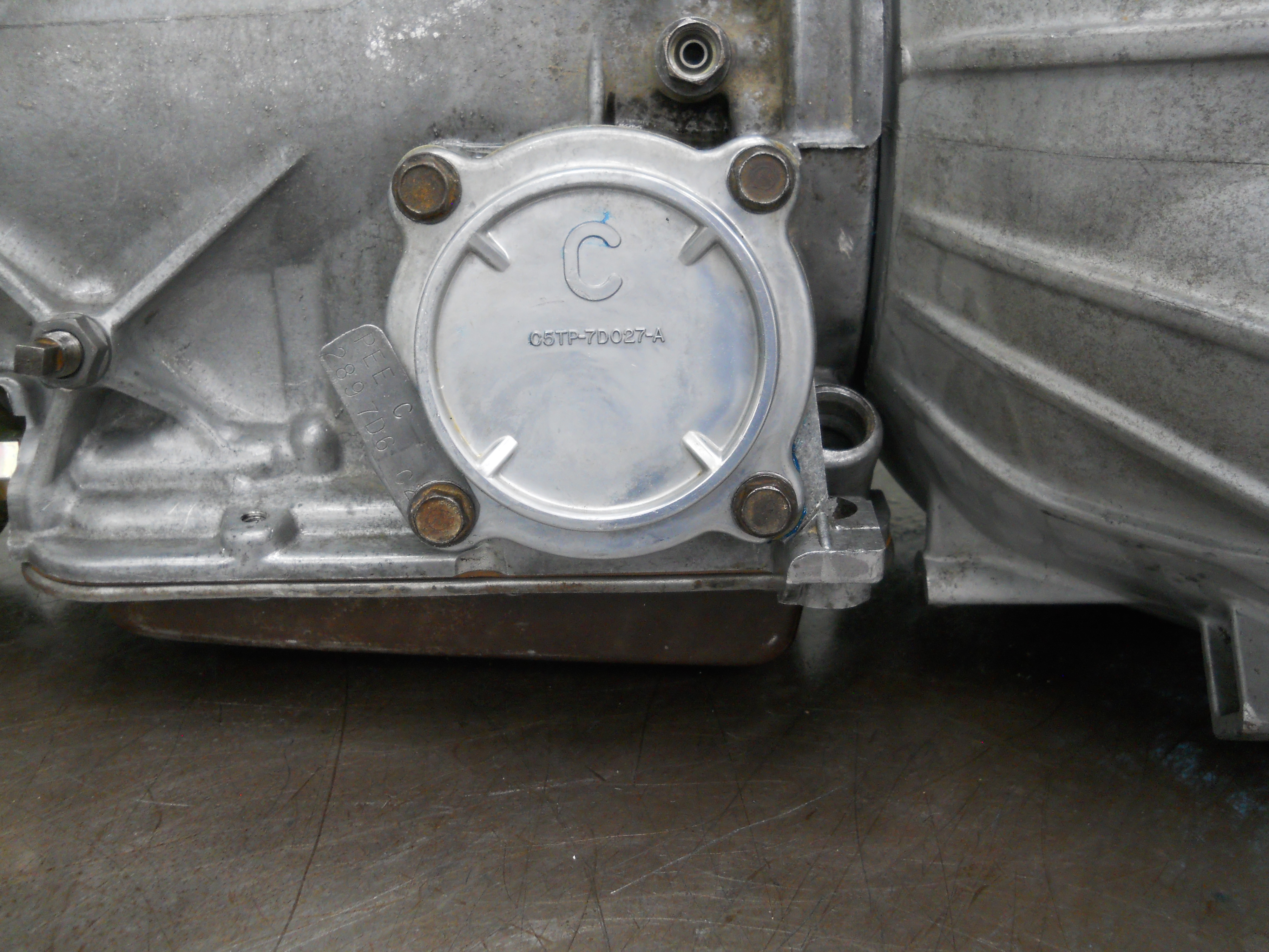
- Intermediate Servo and Cover — The intermediate servo was larger which provided additional area for the piston face and subsequently more force on the intermediate band which resulted in better 1-2 shifts. This servo is identified by a large cast "C" on the cover rather than the "A" that the standard Mustang C4 used. The "A" servo piston is 2.84 inches in diameter and the "C" servo piston is 3.13 inches in diameter.
- Governor — Ford changed the secondary valve in the governor by reducing the weight from about 19 grams to 12 grams, 37% lighter. This moves the wide open throttle shifts points into the 5800 RPM range. Contrary to what has sometimes been reported, Ford DID NOT install a lighter spring in the governor to achieve higher shift points.
Bob Mannel provides an explanation of the function of these modifications in his book Mustang & Ford Small Block V8, 1962-1969, Appendix I:
The throttle pressure boost valve spring was weaker to allow the throttle booster valve to move sooner under wide open throttle when in first gear below 10 mph. The movement of the valve acted to increase pressure which delayed the 1-2 shift.
The weaker intermediate servo accumulator spring allowed earlier movement of the intermediate band accumulator valve to release trapped fluid under the servo piston (exit side) which resulted in faster band application for the 1-2 shift. It also helped provide faster band application on forced 3-2 downshifts.
The separator plate had two holes that were enlarged for high performance application. The bigger of these two holes worked in conjunction with the intermediate band accumulator valve which was trying to get the intermediate band to apply quickly. The larger hole helped expedite the exit of trapped fluid behind the servo piston. The other hole allowed faster timing for 2-3 shift events.
The servo piston was larger. Taking advantage of the faster events, it exerted more holding force on the intermediate band. The larger servo was the reason the servo housing was different.
The governor had a lighter secondary valve. Once the primary valve had moved outward by centrifugal force (at speeds over 10 mph), it provided an exhaust for control pressure coming into the secondary valve, the secondary valve could then regulate pressure back to the main control valve. Because the secondary valve had been lightened, it took less force than normal to hold the valve against centrifugal force, thereby dictating higher speeds before pressure was sufficient to cause 1-2 and 2-3 shifts.1
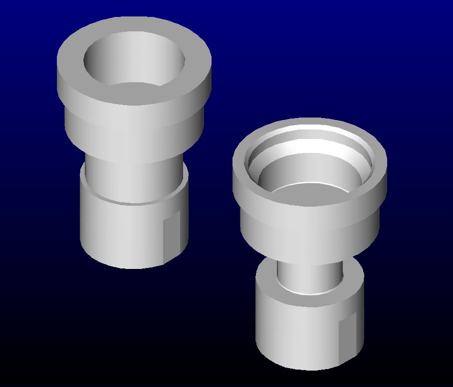
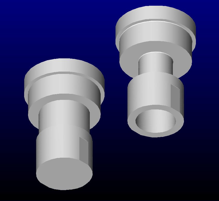
|
Side by side imageges of the standard C4 Secondary Governor Valve (on left) and the Hi-Po C4 Secondary Valve.
Note how much less material is used for the Hi-Po C4 Valve to reduce weight and raise the WOT shift points. |
BACKGROUND ON SFM6S817's TRANSMISSION
At some point in this car's deep dark past, the original transmission was removed for unknown reasons. One guess would be that a previous owner didn't think the automatic was cool enough. And he wanted a 4-speed. So a mid 1960's Ford four speed "Toploader" manual transmission from a Fairlane was substituted in place of the C4 not realizing just how special that automatic was. In order to fit this particular transmission into the car the transmission tunnel had to be chopped to clear the shifter. About as criminal an act as I can think of without getting arested.
In 1979 or 1980, I rebuilt the 1967 C4 (PEE C, date code 7D6-April 6, 1967) I had obtained in a trade for an Offy 360 Intake Manifold with a TransGo® 47-2 shift kit. My thoughts were that was all I needed to do to replicate the shift characteristics of the high performance C4. I did realize that the Hi-Po unit had a different itermeadiate servo and a different governor but there was little I could do about it. I guess I could have ordered thse parts from Ford back in 1980 but I was on a budget and I honestly didn't think to do it.
After I rebuilt the C4, the only problem was that it would shift from 1st to 2nd but not into 3rd. A phone call to TransGo® tech support, determined that I had incorrectly installed a slide valve backwards. Fortunately the valve was just in back of the vacuum modulator and it was an easy task to turn it around. The transmission then opperated normally from then on and gave many years of trouble free service.
Fast forward 40 years. A leak had developed where the manual control lever passes into the case, probably from sitting unused for so long. Fixing the leak was going to require removing the transmission pan so it was looking like I was going to need to pull the transmission out of the car and go through it. Since a rebuild the engine was planned, I felt that this would also be a good time to continue what I started out to do all those years ago. That is to replicate the character of the Hi-Po C4.
RECREATING THE HIGH PERFORMANCE C4 3-SPEED AUTOMATIC TRANSMISSION
Recreating a High Performance C4 was going to require changes in addition to what had allready been done. With the valve body covered by the TransGo® 47-2 Reprograming Kit, the other two changes would be addressed with a reproduction "C" intermediate servo piston and cover manufactured by California Pony Cars and a C4 Govenor Weight Kit which features a reduced weight secondary governor valve designed, produced, and marketed by Dynamic Racing Transmissions who specialize in Ford C4 and C6 transmissions.
TransGo® 47-2 Reprograming Kit
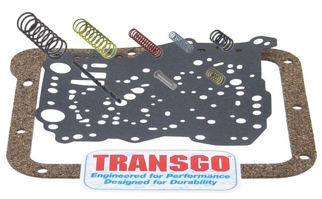
|
| Image coutesy of TransGo® |
TransGo® states the following regarding their 47-2 Kit:2
Shift and hold 1st and 2nd gear to any RPM when manually shifted but retains automatic up shifts in drive position
Features:
- Slightly firmer shifts than #47-1
- Quicker action throughout all shifting
- Firmer shift performance
- Raises overall line pressure
- 75% quicker 2-3 shifts
- More pressure for passing gear between 32-45 mph
Corrects/Prevents/Reduces:
- Too easy/too often passing gear
- No reverse hot
- 1-2 slide
- Soft 2-3
- 3-2 cut-loose
- 3-2 shuttle
- 2nd band failure
|
| NOTE: The TransGo® 47-2 Reprograming Kit does not signifficantly raise wide open throttle (WOT) shift points. WOT shift points are controled by the governor. |
California Pony Cars "C" Servo Piston & Cover Kit
C5AZ 7D022-C, Piston - Intermediate Band Servo (Casting No. C5TP-7D022-A)
C5AZ 7D027-B, Cover - Intermediate Band Servo (Casting No. C5TP 7D027-A)
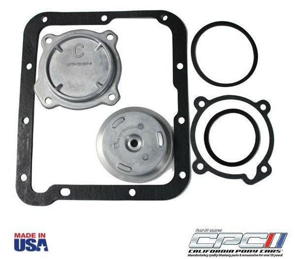
|
| Image coutesy of California Pony Cars |
Here is what CPC has to say about their C4 Servo & Cover Kit:3 "C" Servo Piston & Cover Kit for 1965, 1966, 1967, 1968, 1969, 1970, 1971, 1972 and 1973 Mustangs with a C4 Transmission. This is the transmission that came in the factory equipped SHELBY GT-350 and other Hi-Po cars. Kits comes complete with all gaskets and seals (including a pan gasket) required for installation. The piston diameter is slightly larger than the standard unit providing an increase in surface area. This provides a firmer application of the intermediate band, or simply a quicker, cleaner, firmer 1-2 shift. The piston and cover unit will replace the standard "A" unit without any modifications.
|
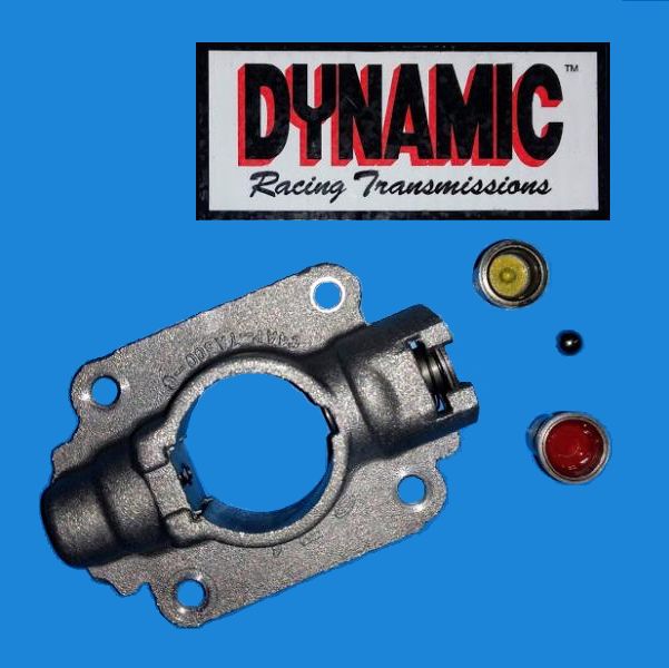
Dynamic Racing Transmissions C4 Govenor Weight Kit
|
| Image coutesy of Dynamic Racing Transmissions |
DRT says this with respect to the C4 Govenor Weight Kit:4
After several months of R&D, we have developed a kit for street drivers and racers that run full automatic C4 valve bodies.
The kit allows for the fine tuning of the wide open throttle shift points to attain the rpm needed for best performance.
Included in the kit is a refurbished governor valve casting, three lightened secondary weights, a 1/4" checkball and complete instructions.
Installation requires removal of the tail shaft housing to gain access to the governor assembly.
No machining or special tools required.
Additionally, the installation instructions has this explanation regarding the valves supplied in the kit:
Proper Secondary Weight Selection
The 12 gram weight that is pre-installed in the new governor is designed after the 289 HiPo valve offered by Ford in the late 60's. Its weight was determined based on the standard 19 gram weight found in most passenger vehicle C4 governors.
It should provide wide-open thottle shifts in the area of 5800 rpm. If you want to shift higher, we have provided the Yellow weight which is 11.5 grams. This will give you an additional 200 rpm over the 12 gram value. The Red valve is 12.5 grams and will reduce the rpms 200 from the 12 gram rating.
The supplied spring is a stock rate spring.
|
TRANSMISSION REMOVAL - September 19, 2021
The first step in the rebuild is of course getting the transmission out of the car. My friend Greg Catanzano, who is an automatic transmission wiz doing online tech support during the day and teaching auto mechanics at night at the local tech school, came over to help finish removing the C4. Actually I ended up being his assistant as he took charge. Once the transmission was out, Greg pulled the torque converter down and pronounced it trashed. He told me that the torque converter would have to be refurbished and that this would give us the opportunity to make sure that the stall speed is properly set.
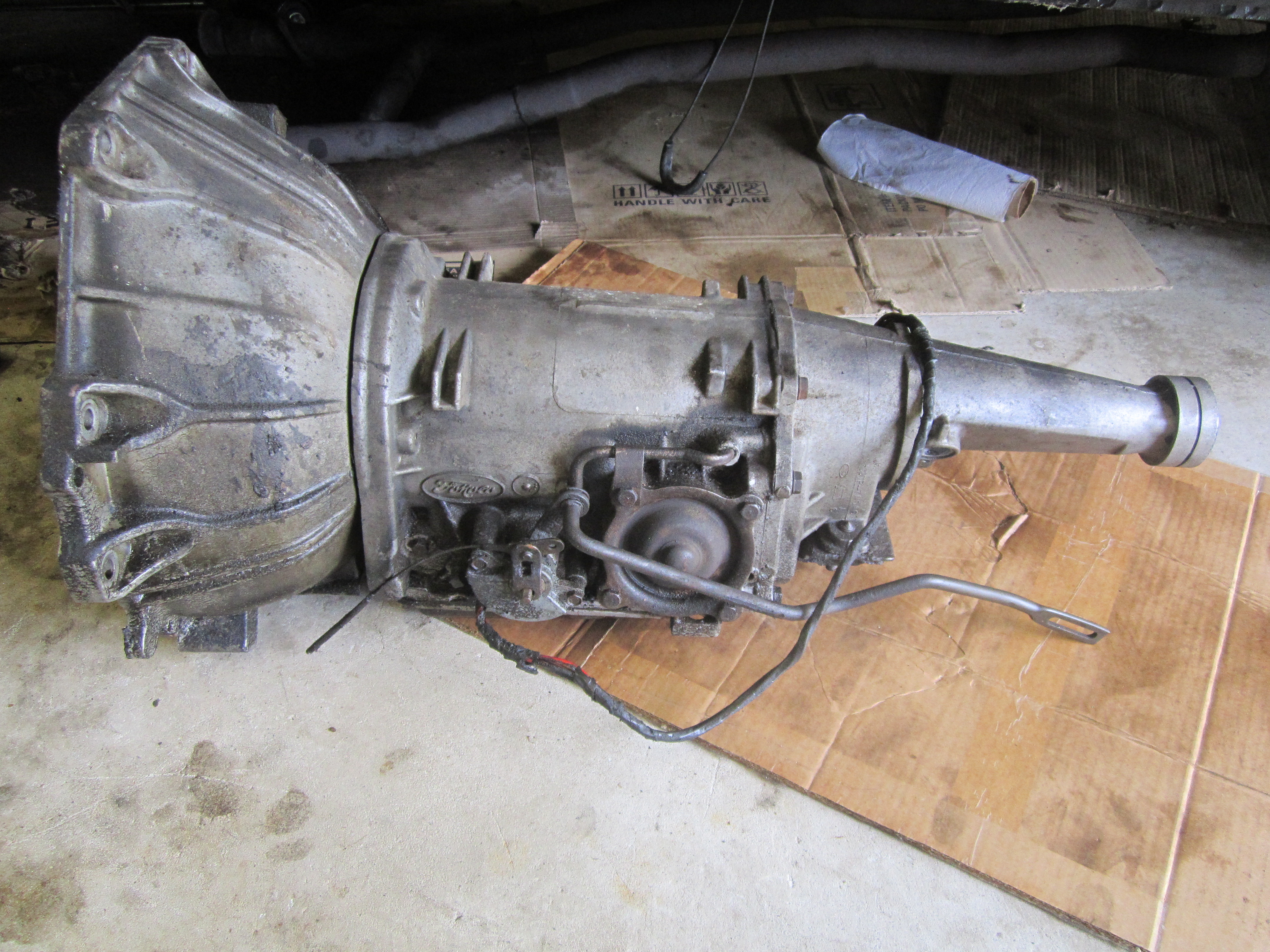
| 
|
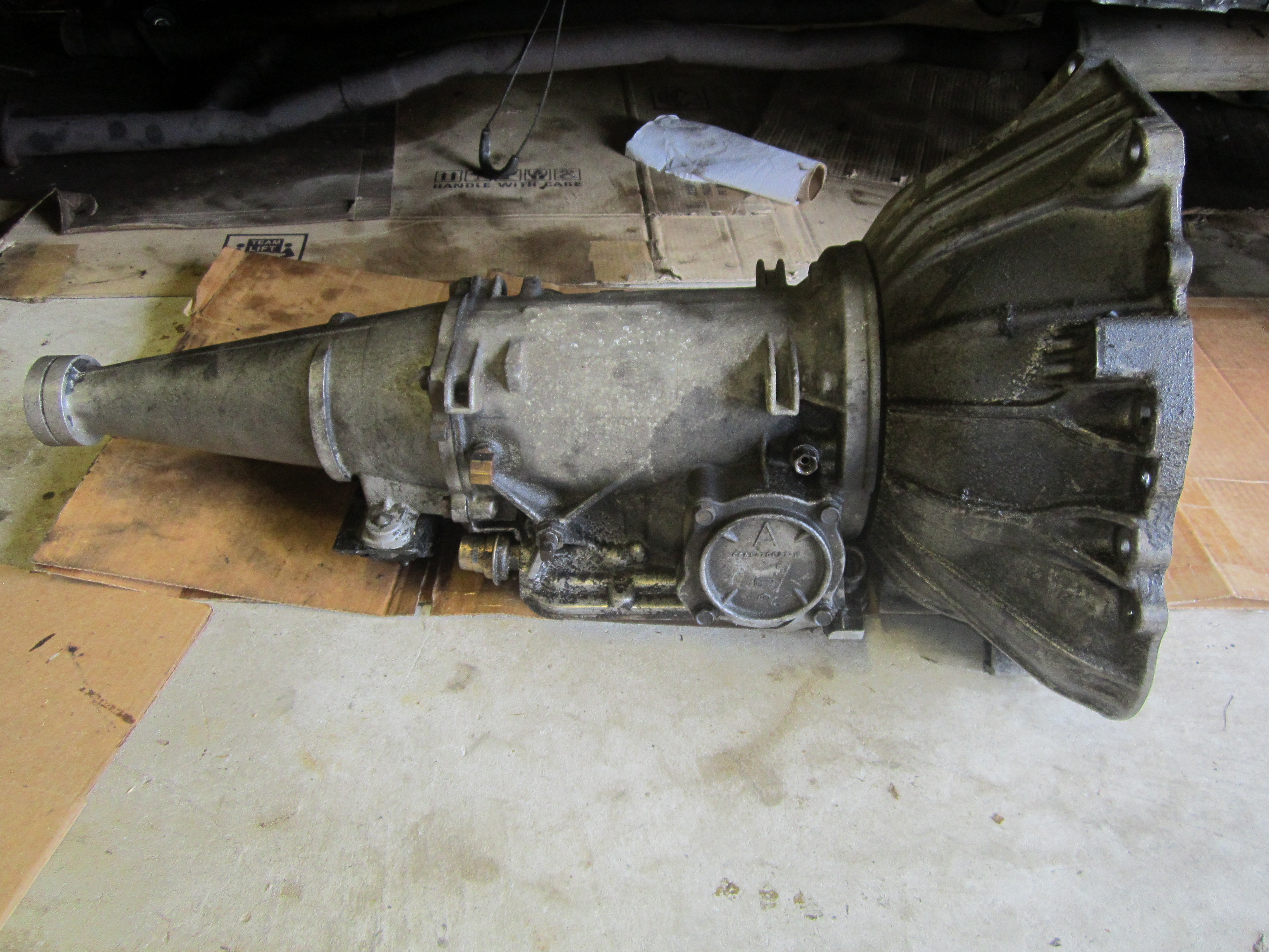
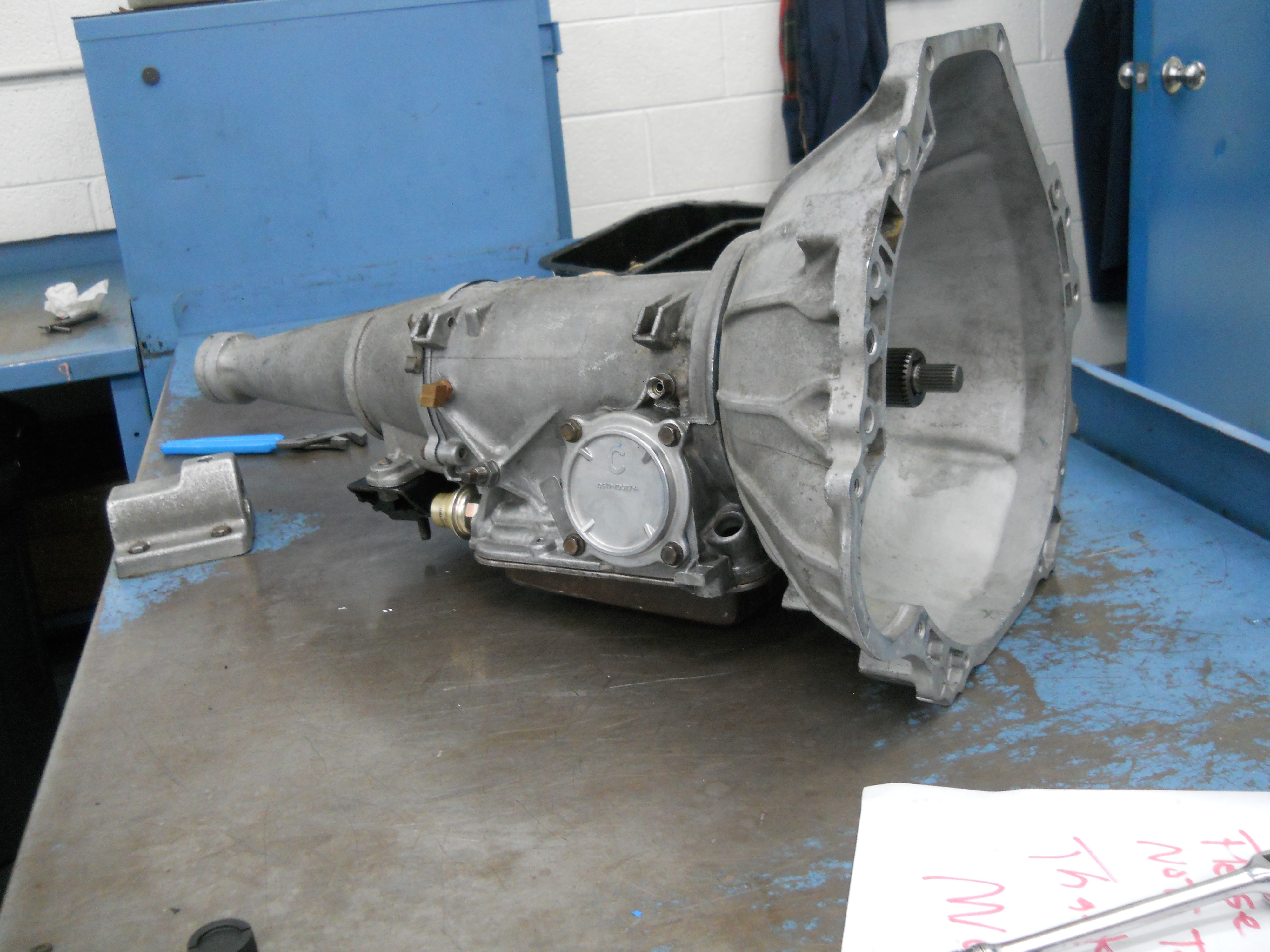
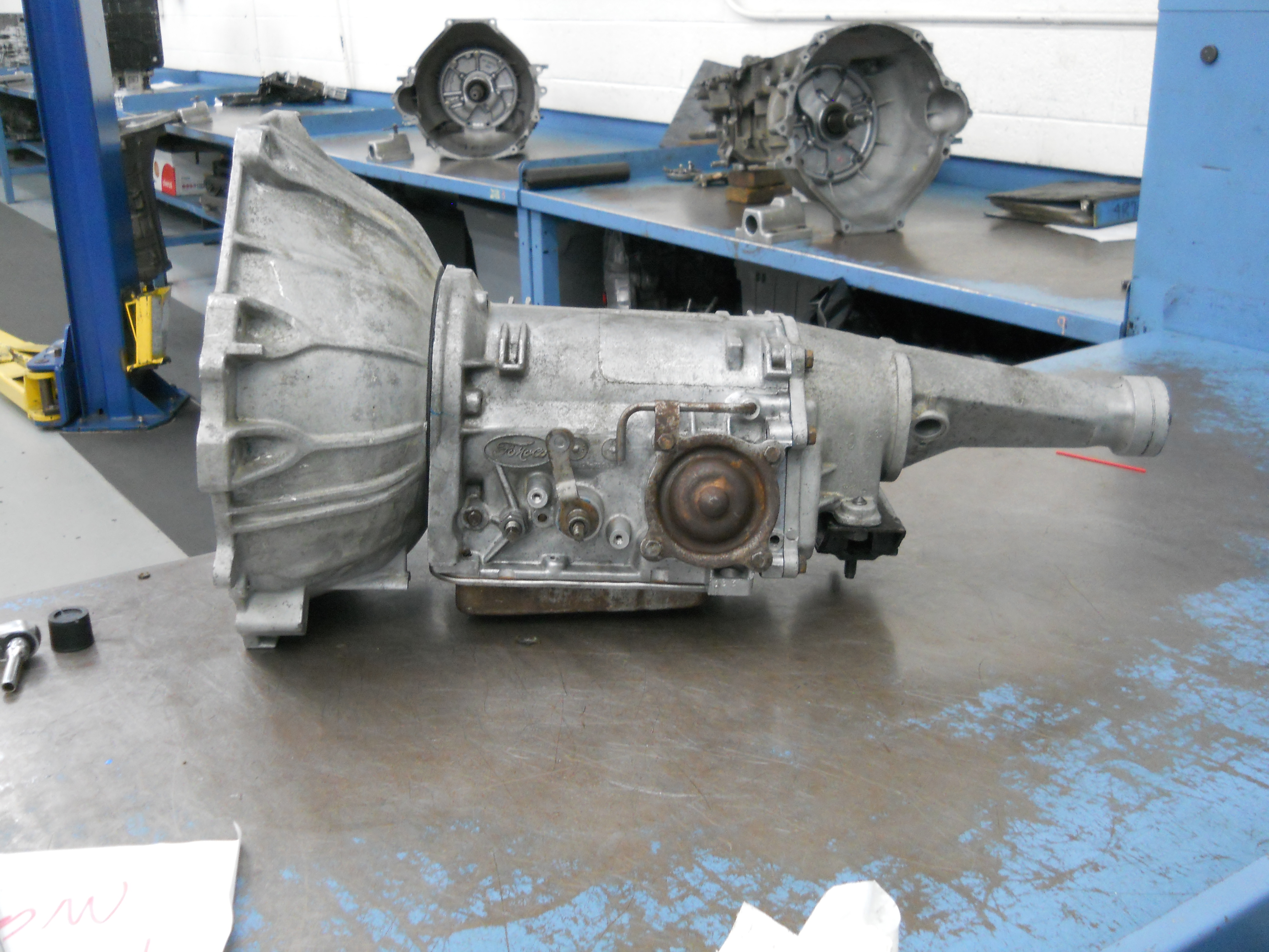
| C4 Left Side | C4 Right Side |
| The C4 covered in grease and grime that has been accumilating since 1980. This was due to multiple leaks at the heads and rear of the intake manifold seeping down onto the transmission. The neutral saftey switch and the shift lever arm rod (C7ZZ 7326-B, Rod - Transmission Manual Control Selector Connecting) are still attached in this photo. | Note the "A" code intermediate servo cover on the right side of the transmission. This will be replaced by the much more robust reproduction "C" servo piston and cover during the rebuild.
|
| 
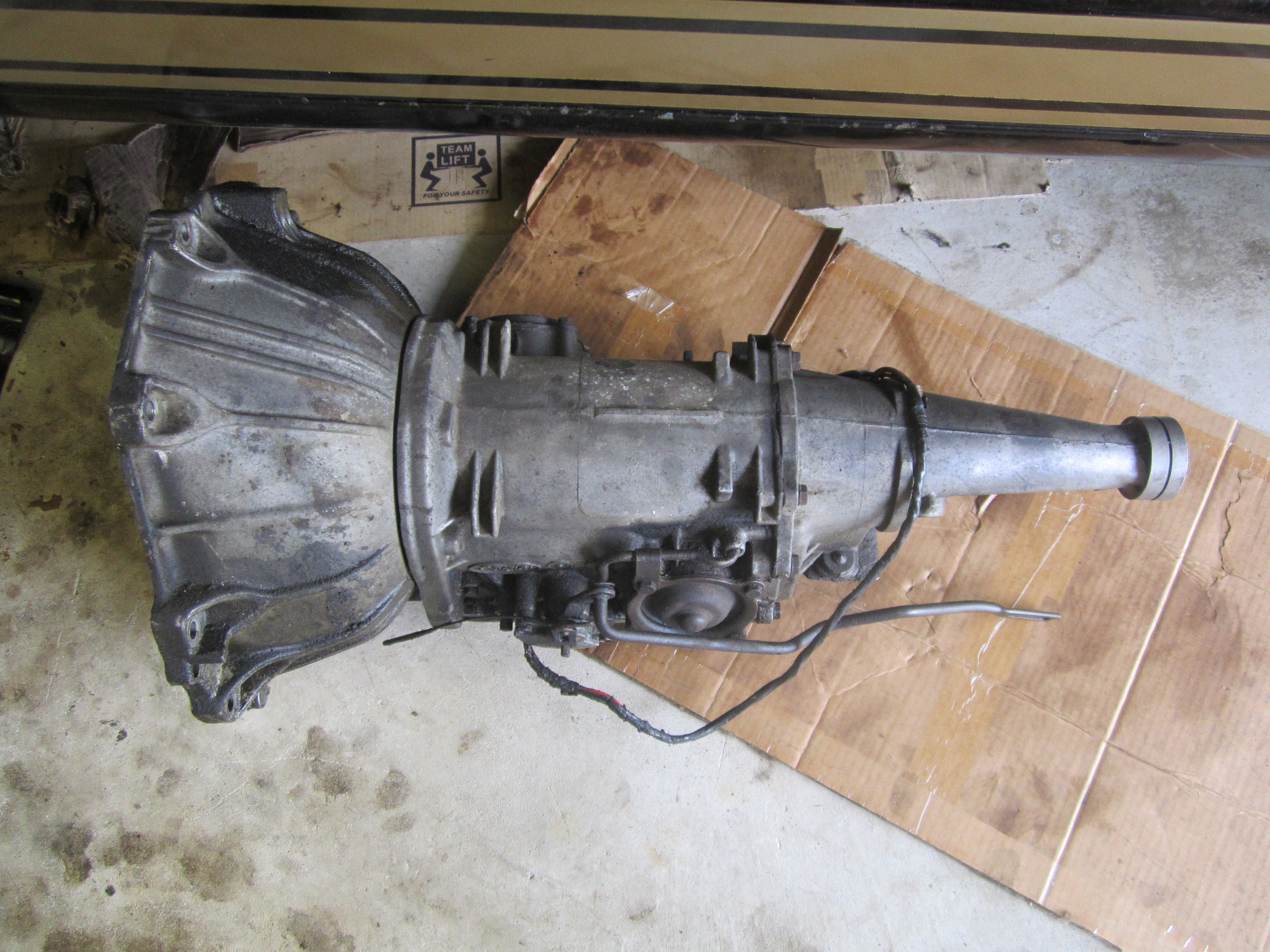
|
| C4 Top | C4 Data Tag |
| The C4 is pretty dirty regardless of the direction you veiw it from. | This PEE C coded transmission was designed for a stock 2-barrel or 4-barrel 289 Mustang. Nothing High Performance in its make-up. The date code 7D6 decodes as April 6, 1967. |
I'll not go into any great detail here but the following things (in no particular order) had to be removed/disconnected in order to remove the transmission from the car:
- Bell Housing Bolts
- Dip Stick and Bolt
- Left Side Header
- Exaust System Pipes
- Starter
- Parking Brake
- Transmission Cross Member
- Drive Shaft
- Transmission Fluid Cooling Lines
- Shift Linkage
- Nuetral Safety Switch
- Inspection Plate
C4 TRANSMISSION REBUILD PREPARATIONS
Separator Plate Gasket - February 26, 2021
Since I was going to need a new separator plate gasket, I placed a call to Trans-Go and explained that I had used their 47-2 kit about 45 years ago and would they be able to supply a gasket to me? To my surprise, the said they would supply me with one, free of charge. Now that is what I call customer service! This gasket is somewhat different than the stock version as it has some additional holes to accomodate changes in the separator plate. They also supplied me with a PDF copy of the installation instructions, again free of charge.
C4 Trans Tips - October 3, 2021
I sent Steve McDonold, fellow Hertz car owner and SAAC member a message regarding the kickdown linkage since I'd never set it up before. Guess I didn't think I needed it. Steve sent me not only the requested information but also some tips he had learned while working on C4s over the years. Here is the text of his message:
I used to work at a Lincoln Mercury dealer and was the trans guy.
I probably have done hundreds of C4's as they put them in everything, when they started putting cat convertors on car they seemed to die with regularity. When I redid my car in the early 2000's we decided to reseal the transmission.
The original C4s for the 289 HiPo has special parts, including the valve body, governor, output shaft (because of the lower ratio rear end, related only to the speedometer gear), torque convertor. The original front pump gasket was made of a white asbestos like material and held the front pump in like it was welded in. Do not make the mistake of hitting in the stator of the front pump, it will snap off. We used to take the 2nd gear band struts out and use a modified long punch and there was a spot you could beat on the back side of the pump through the inside of the case to get it loose.
Most, if not all of the newer front pump gaskets are made of a real thin material and the rectangular pump openings are a tad bit larger (we think they are made that way for use on the C5 also). This causes them to leak. The design is that when sitting, the level in the torque converter will cause the level in the trans to rise. The original square cut rubber O ring would hold the fluid back from leaking. I had my transmission in and out about 4-5 times in a period of about a month attempting to stop the leak. Was finally able to get it to stop by doing the following: Use a little JB Weld and seal that little drain back hole at the bottom of the case (see photo below) and 2nd thing, get a front pump gasket from the following company:
http://www.performanceautomatic.com/contact.php
You have to call them to get the gasket, it about 3 times the thickness of the replacement gasket available today.
Good luck and I'll follow your journey on line.
Regards
Steve McDonald
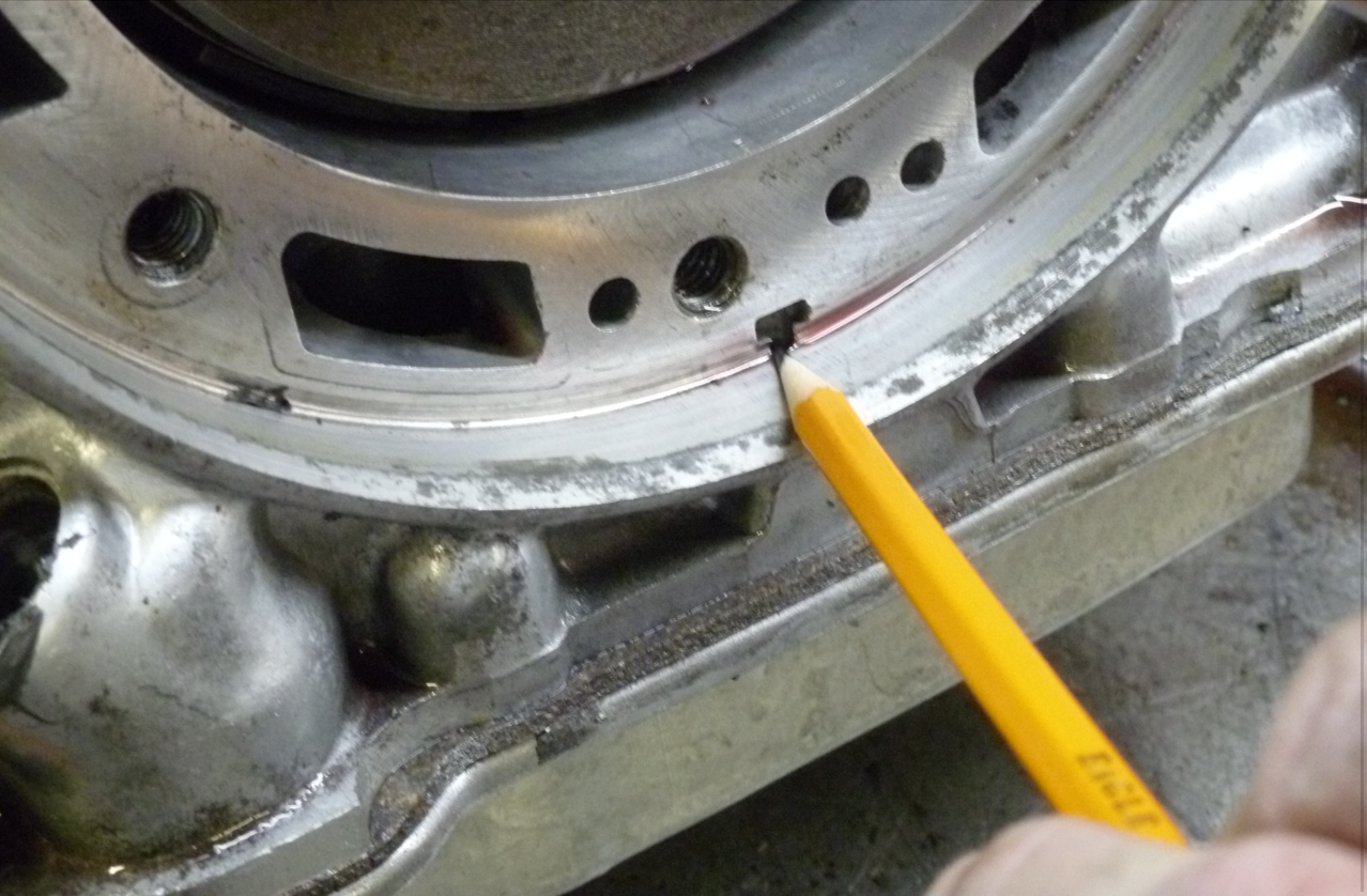 |
| Photo coutesy of Steve McDonald |
| Steve points out the area that is subject to leaking. |
Initial Cleaning and Tear Down Update - October 26, 2021
Greg texted me the following:
- OK, tore it down last night
- Every bushing is bad
- Pump looks worn
- Front Planet Torrington bearing feels bad
- Have to give it the once over tonight and see what parts need to be replaced
- Did not have white pump gasket
- Had aftermarket black
- Was rebuilt before
So I'm the one responsible for the previous rebuild circa the 1979/1980 timeframe. If I remember correctly, I used a standard TRW kit or it could have been a Ford kit. However, I can't find a receipt for the parts. Still my efforts couldn't have been that bad. It did hold together for 45 years or so. No too bad for someone who had never touched the insides of an automatic transmission before!
Per Steve's recommendation, I ordered an Extra Thick C4 Pump Gasket (P/N SP26202) from Performance Automatic which arrived the next day. $22.00 + Shipping.
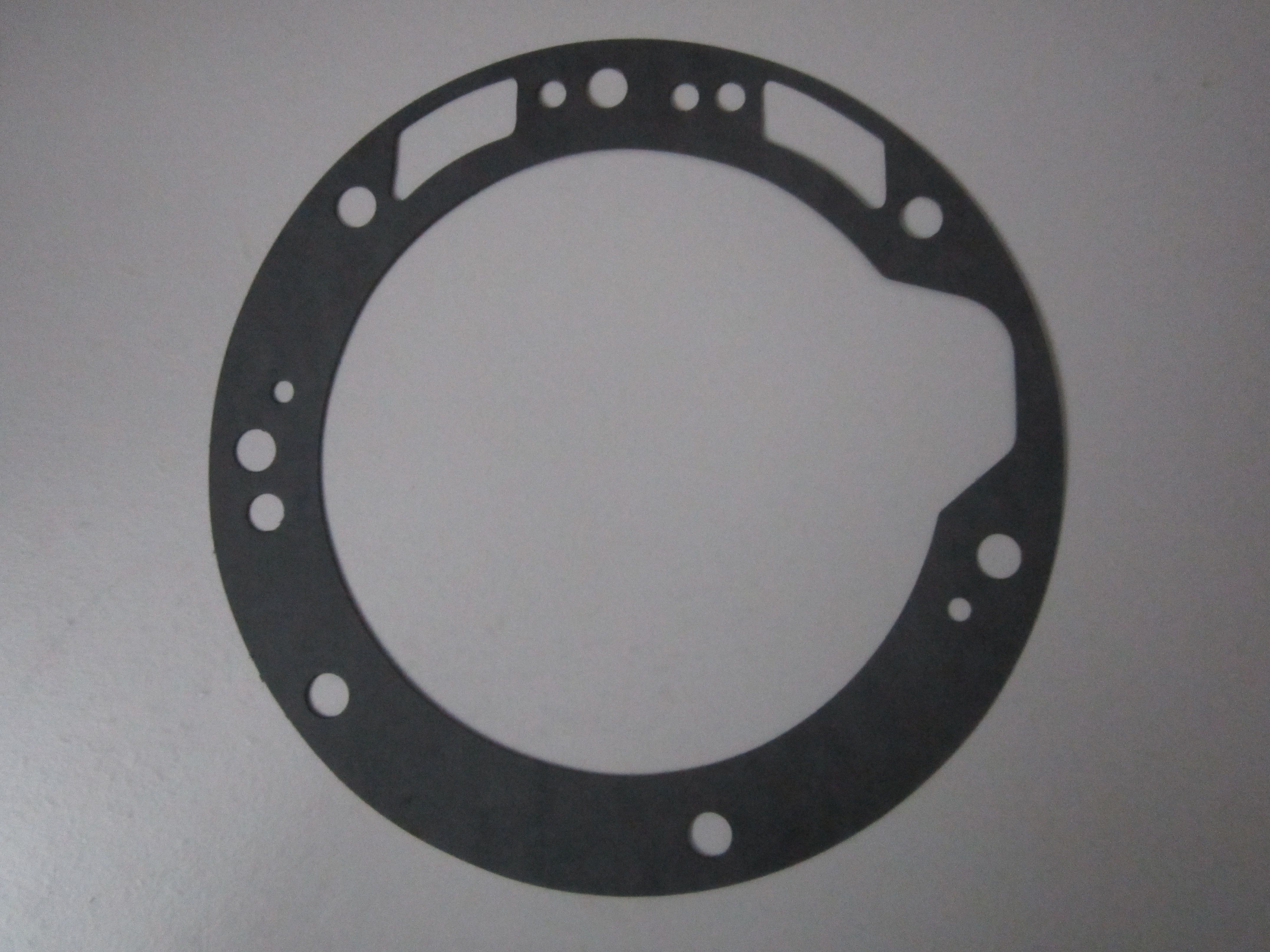 |
| Pump Gasket. |
C4 Replacement Parts Order - October 27, 2021
Greg ordered the following from Transparts Wharehouse and Transmission Parts Distributors:
| P/N | Part Name |
| 025901HP_DLX | C4 Ford Alto Red Eagle & Kolene Transmission Rebuild Kit Deluxe w/ Band 1964-69 |
| 26030 | Bushing Kit, C-4 1964-69 |
| 26200 | Washer Kit, C-4 1964-69 |
| A26530 | C4 & C5 TRANSMISSION PUMP GEAR SET FITS '64-'86 FORD MERCURY LINCOLN |
| 26912 | C4 & C5 TRANSMISSION REVERSE SERVO PISTON BY FEDERAL-MOGUL FITS '64-'86 FORD |
| A26654K | C4 & C5 TRANSMISSION SPRAG KIT: SPRINGS & ROLLERS FITS '64-'86 FORD (C4AZ-7D098A) |
These are all pretty much premium parts. No skimping on quality here!
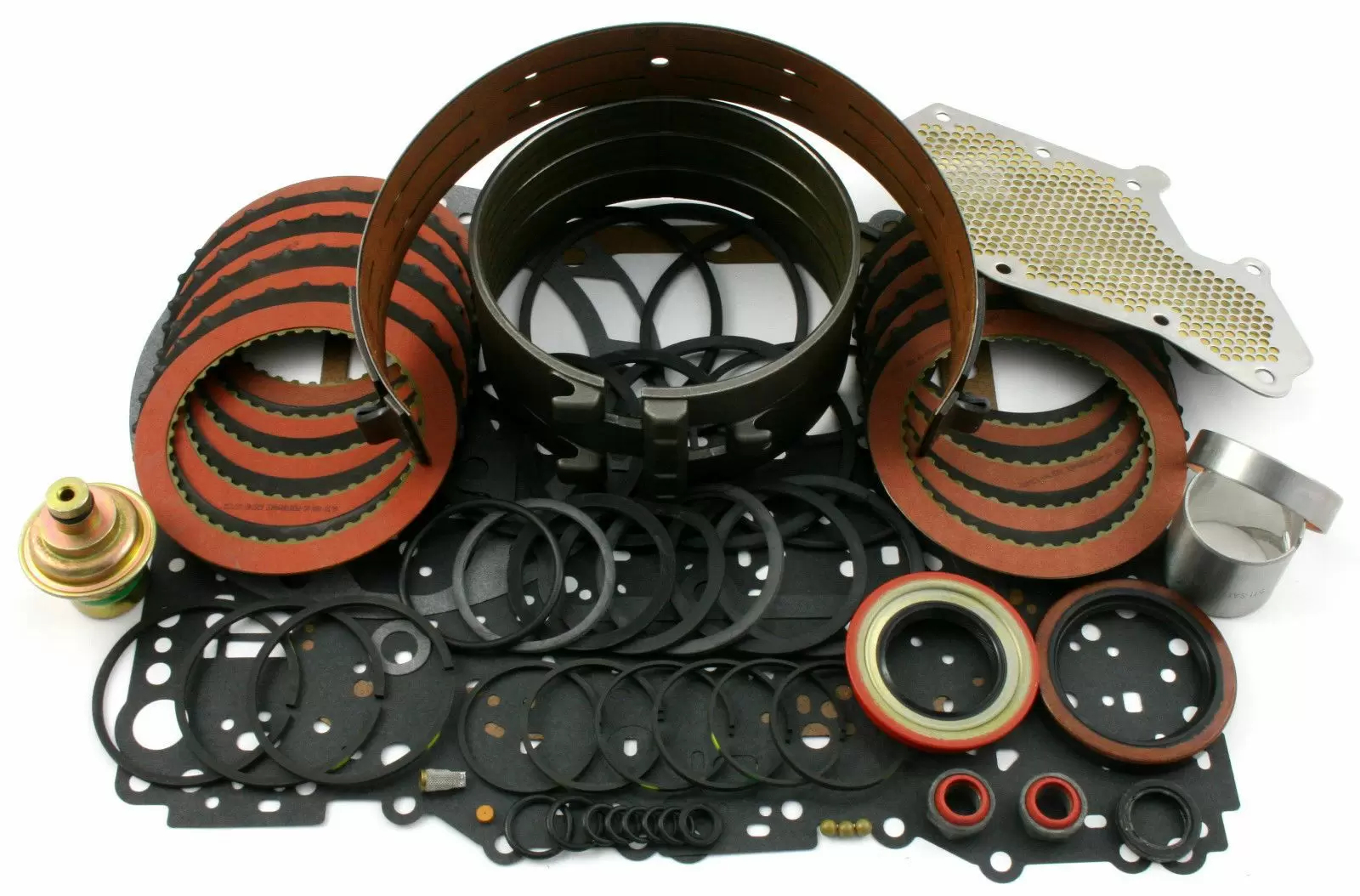 |
This is the transmission master overhaul kit selected for the C4 transmission. It is a "Hi Performance" kit. The friction plates for the forward and direct clutch drums are Alto Red Eagle friction plates. These friction plates are made using a material with a high coefficient of friction. This ensures that the clutch pack does not slip when applied. The 2nd gear band, or intermediate as Ford calls it is also lined with the same Alto Red Eagle material. The Low/reverse band is lined with Kevlar. Kevlar has been used for years in drag racing on ridged style bands. The steel for the clutch drums are Kolene steels. A black coating keeps the frictions from sliding across the steel when applied. The kit contains all new internal and external rubber seals as well as a new oil screen and vacuum modulator. |
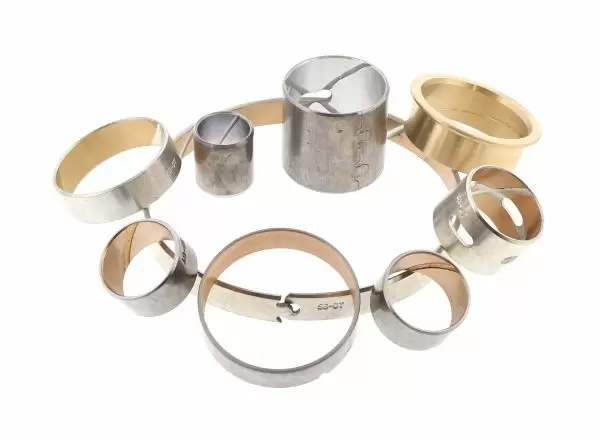 |
This is the bushing kit for the transmission. Bushings are like engine bearings in that they control oil pressure in the transmission. They also serve to hold the center line of the transmission true from the input shaft to the output shaft. Some of the bushings were the original to the transmission from 1967. All bushings were removed and replaced with new ones. |
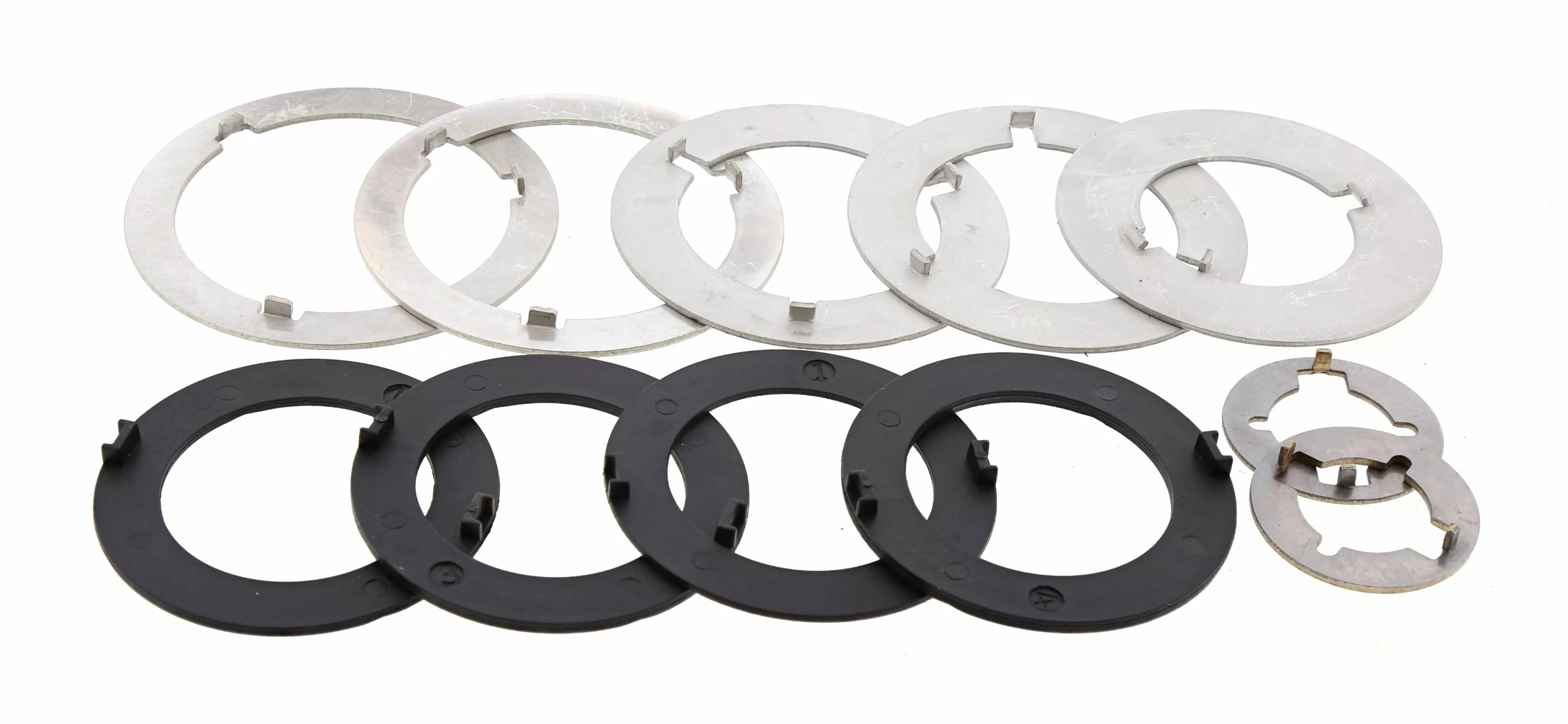 |
| This is the washer kit for the transmission. Washers are used to keep rotating parts from contacting each other. The small black plastic ones are used to adjust and set input endplay in the transmission. The washers were from the previous rebuild in 1980 and had wear on them, so a new set was installed. |
C4 TRANSMISSION REBUILD (October - Novermber 2021)
The transmission rebuild for SFM6S817 happened in October and November 2021 and was handled by my friend Greg Catanzano. Greg has pretty much worked with automatics his entire professional carrer. The rebuild was took place at Universal Technical Institute (UTI) and served as an example for the students for older transmissions.
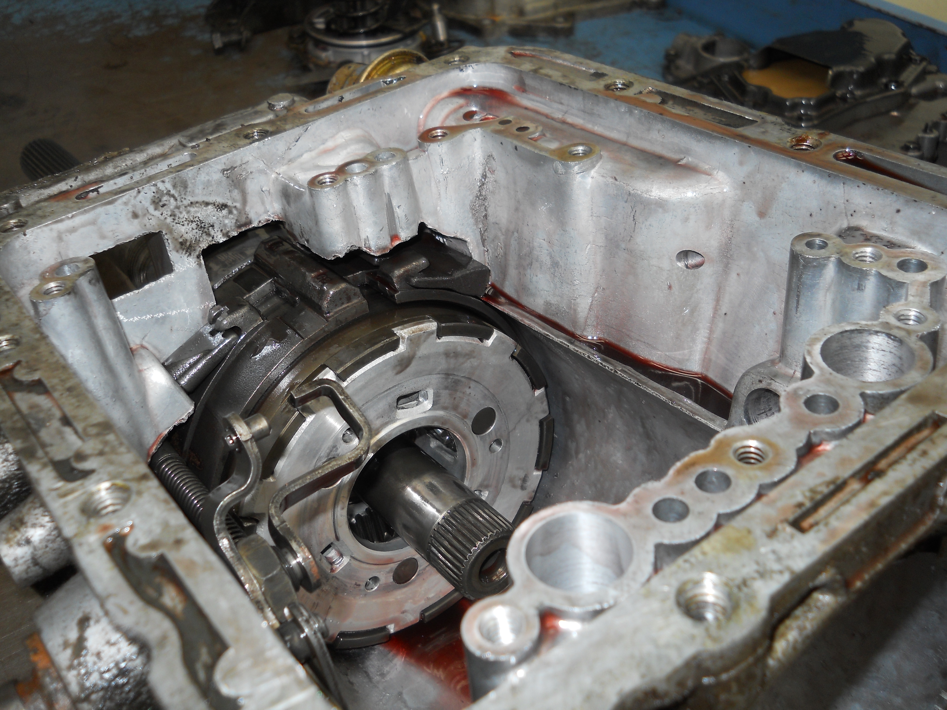
DISSASSEMBLY - October 25, 2021
 |
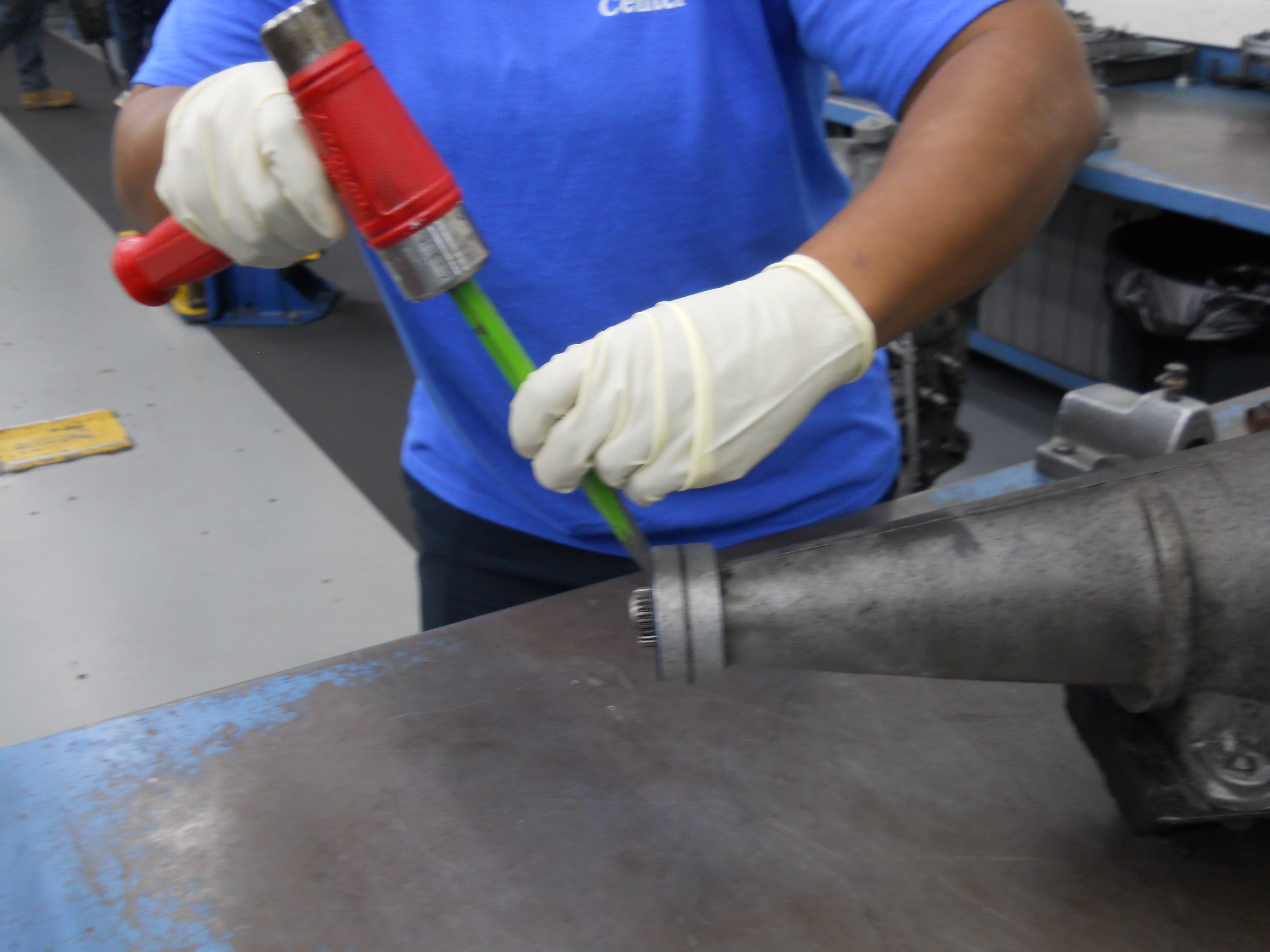 |
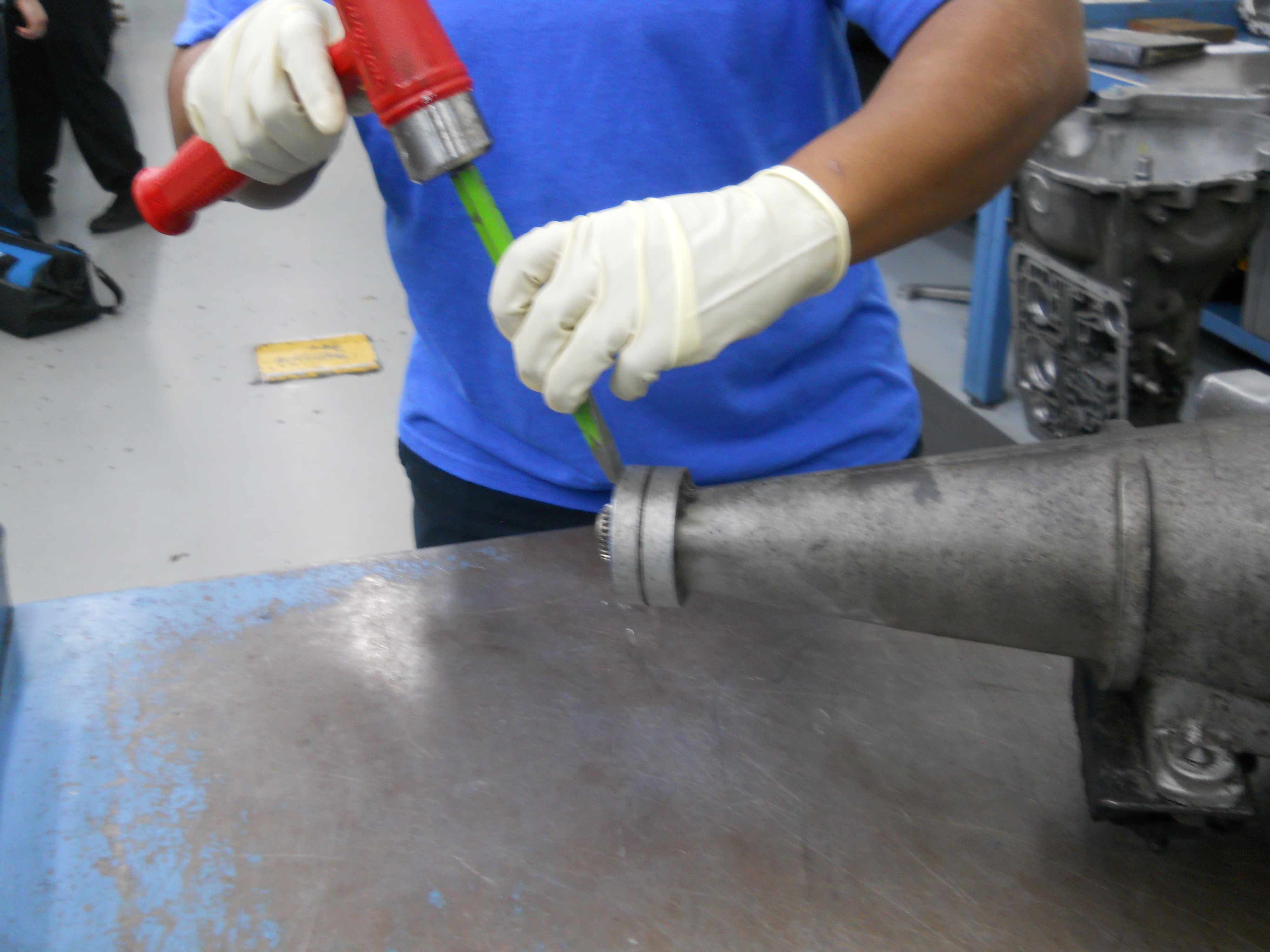
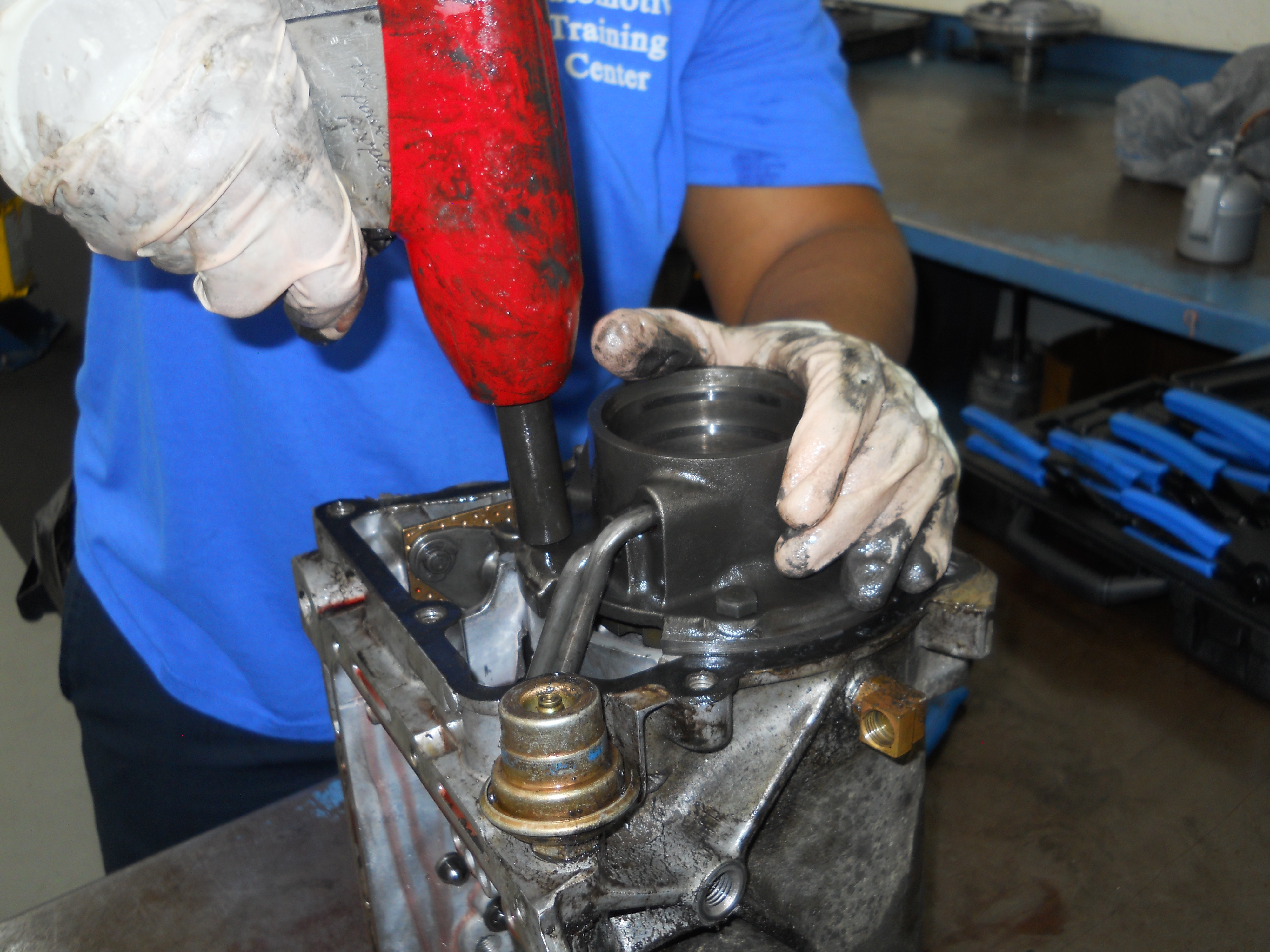
Rear Seal removal — A chisel and mallet are use to remove the rear seal.
[C4-DSCN2771 / C4-DSCN2772] |
|
|
 |
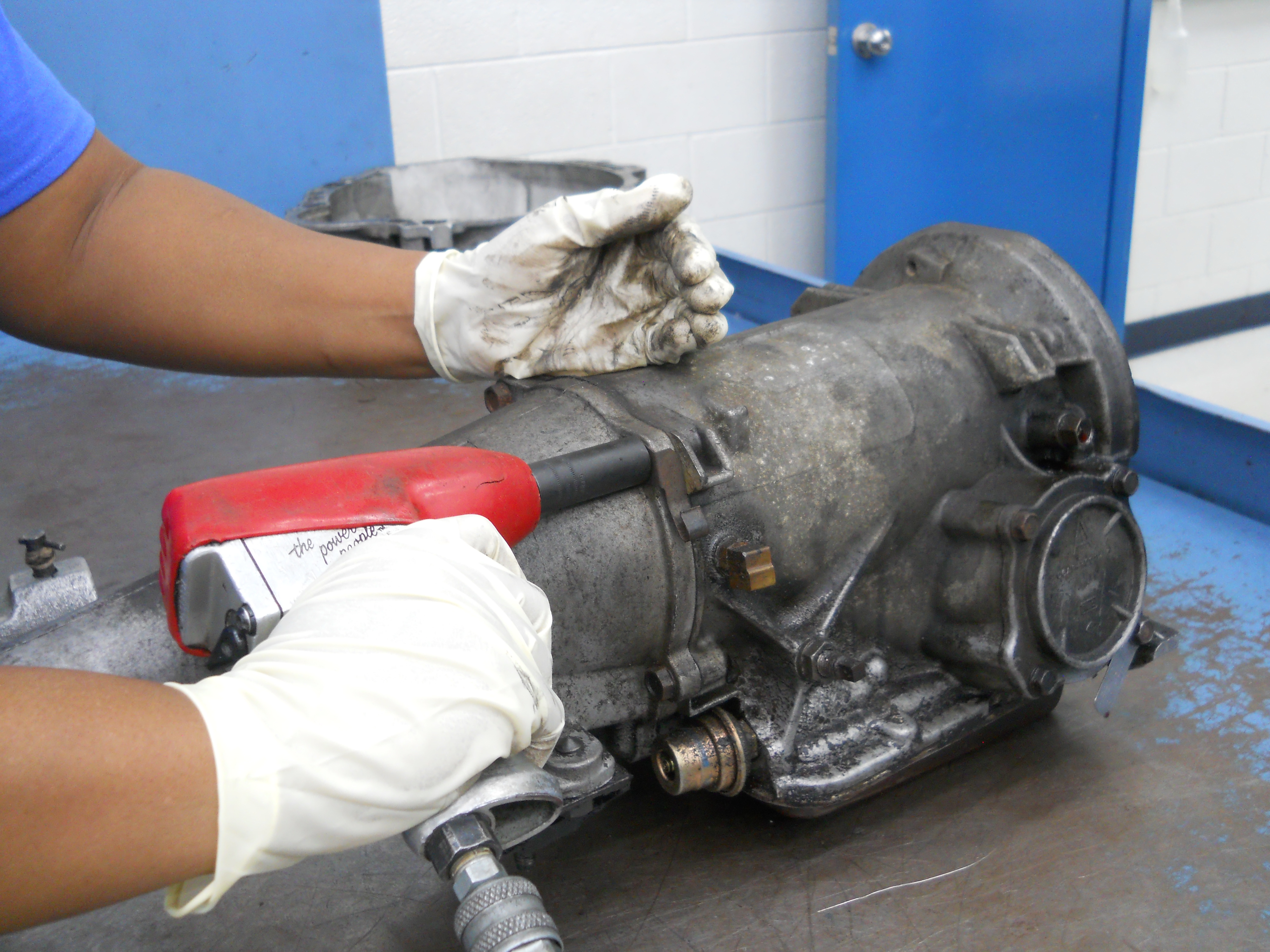 |
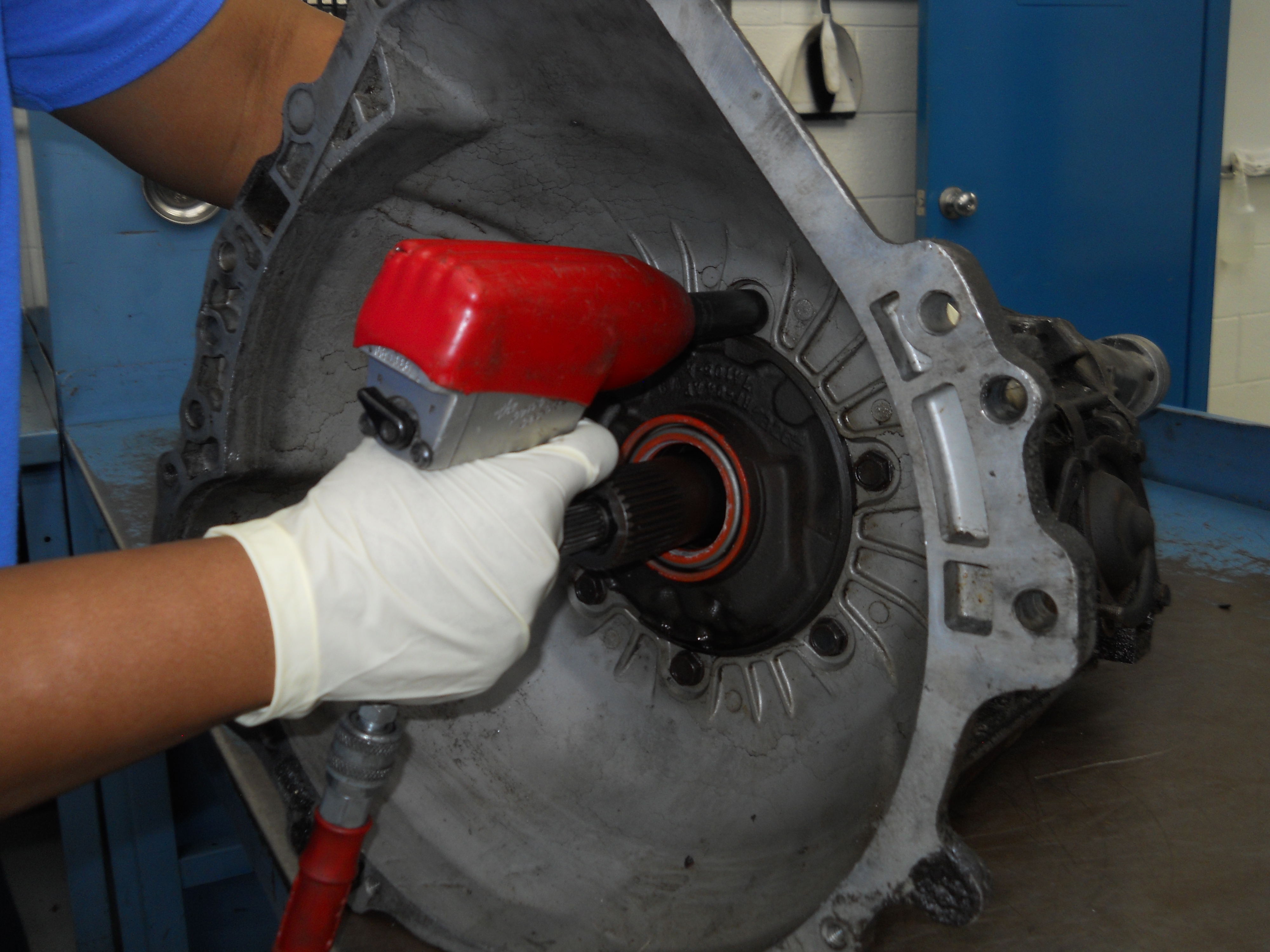
C4 Bell Housing removal. A ⅜ impact wrench makes quick work of removing the bolts.
[C4-DSCN2774] |
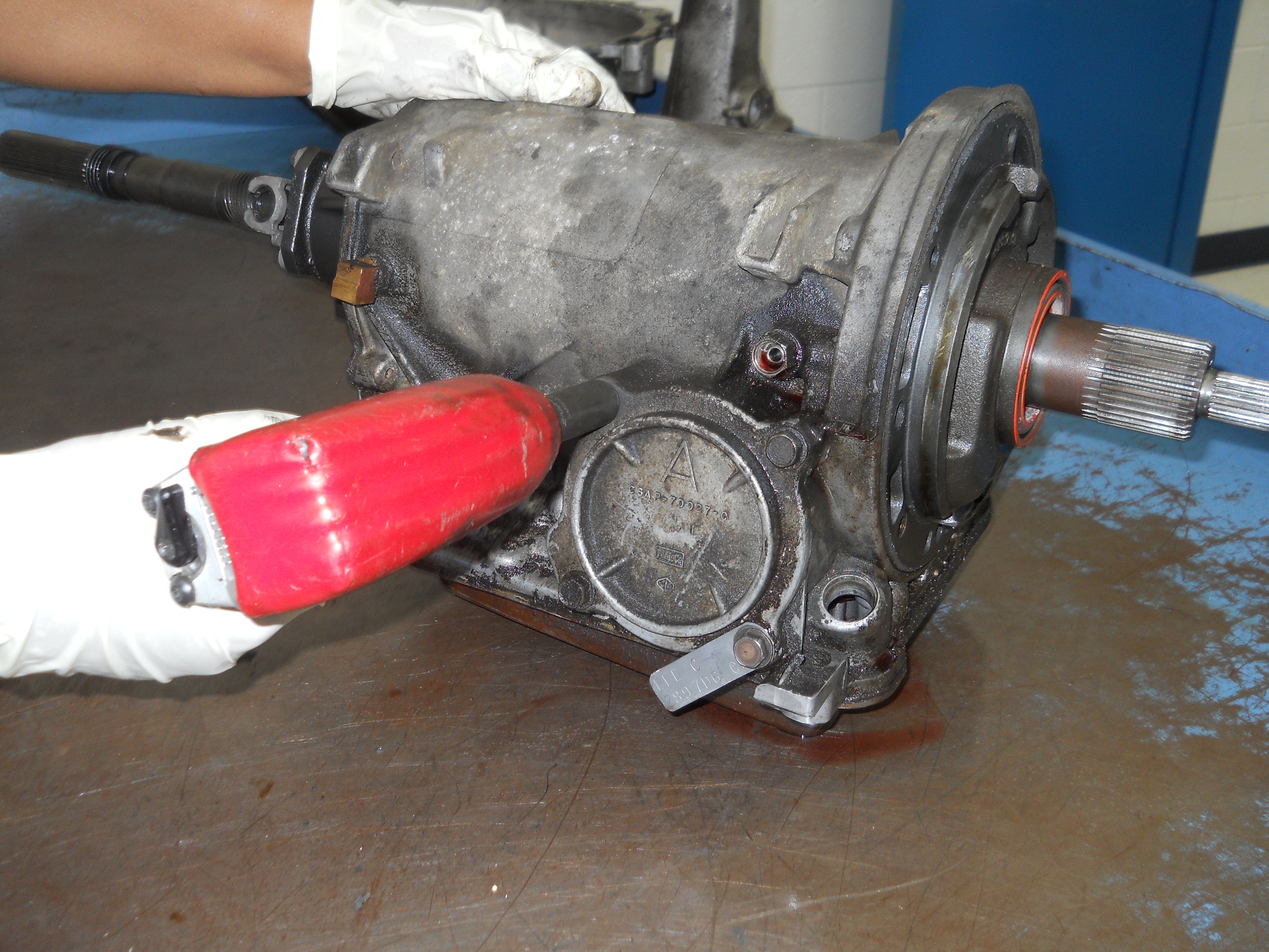
Extension Housing removal. Once again, an impact wrench quickly removes the attaching bolts.
[C4-DSCN2775] |
|
|
 |
 |
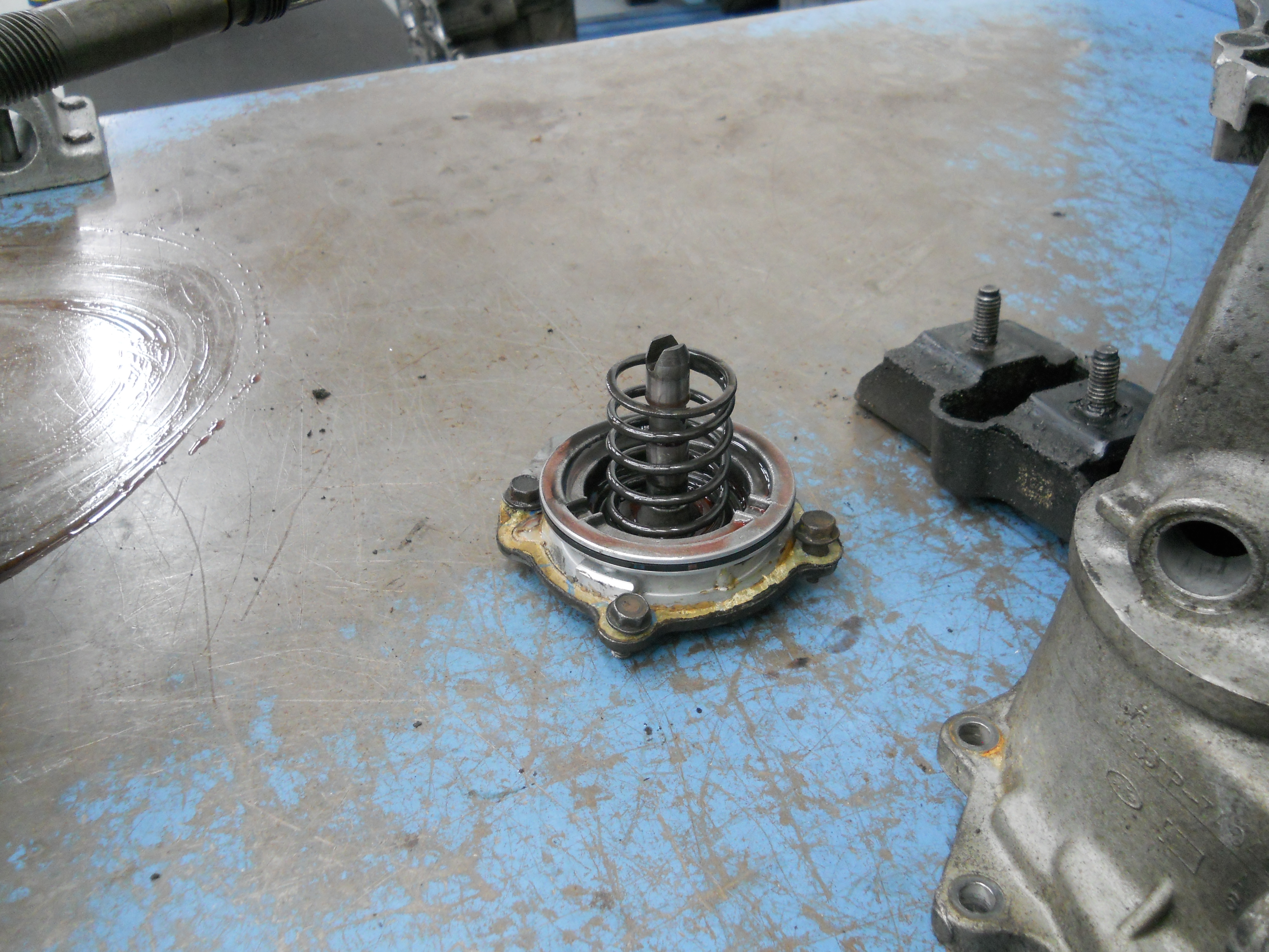
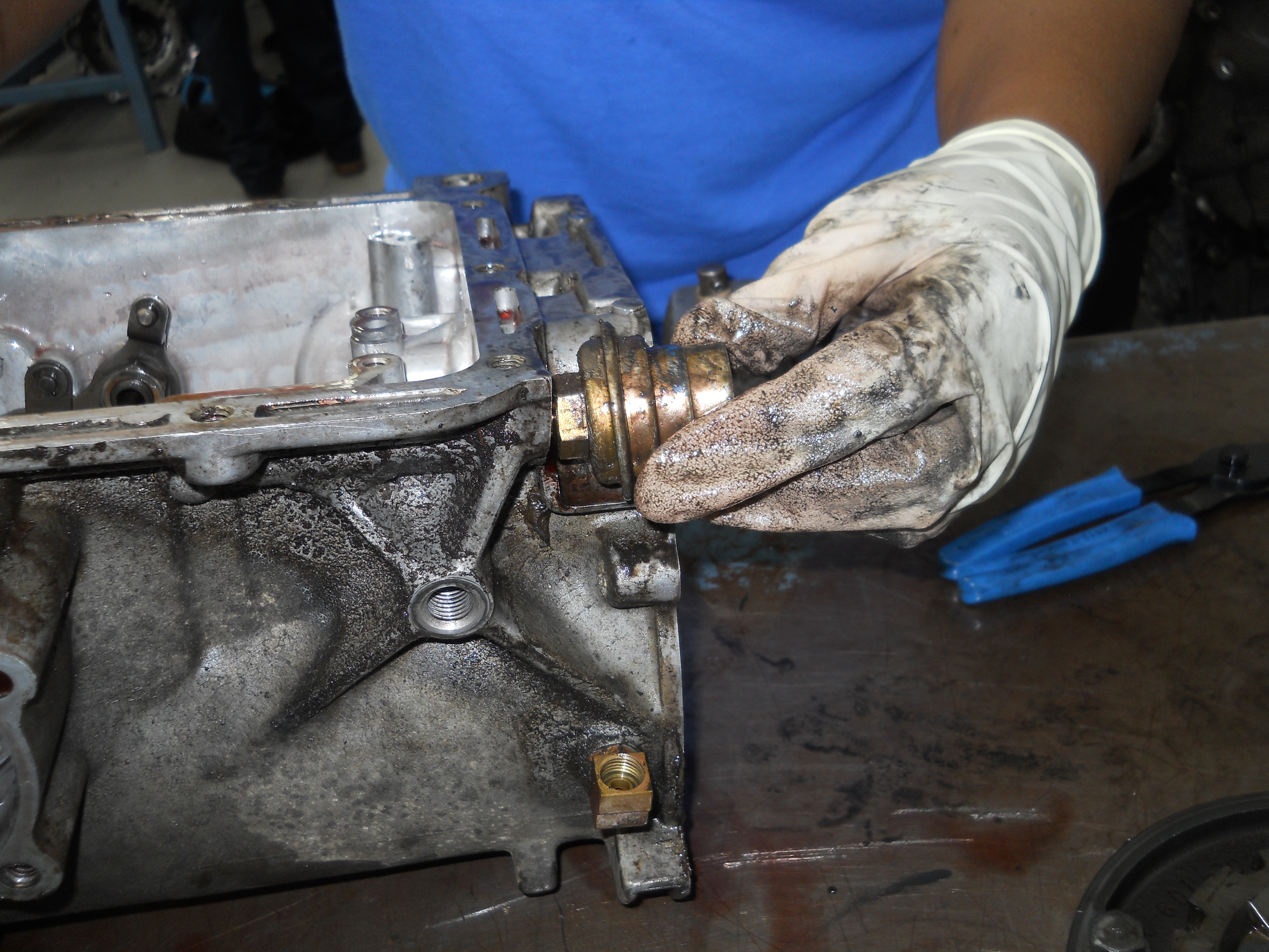
Intermediate Servo Cover and Piston removal. Four bolts hold the servo cover to the case which in turn retains the servo piston.
[C4-DSCN2777]
| Low-Reverse Servo and Piston removal. This cover is pressed steel instead of die-cast aluminum like the Intermediate Servo Cover. Same deal as with the Intermediate Servo, the cover holds the piston in place.
[C4-DSCN2780]
|
 |
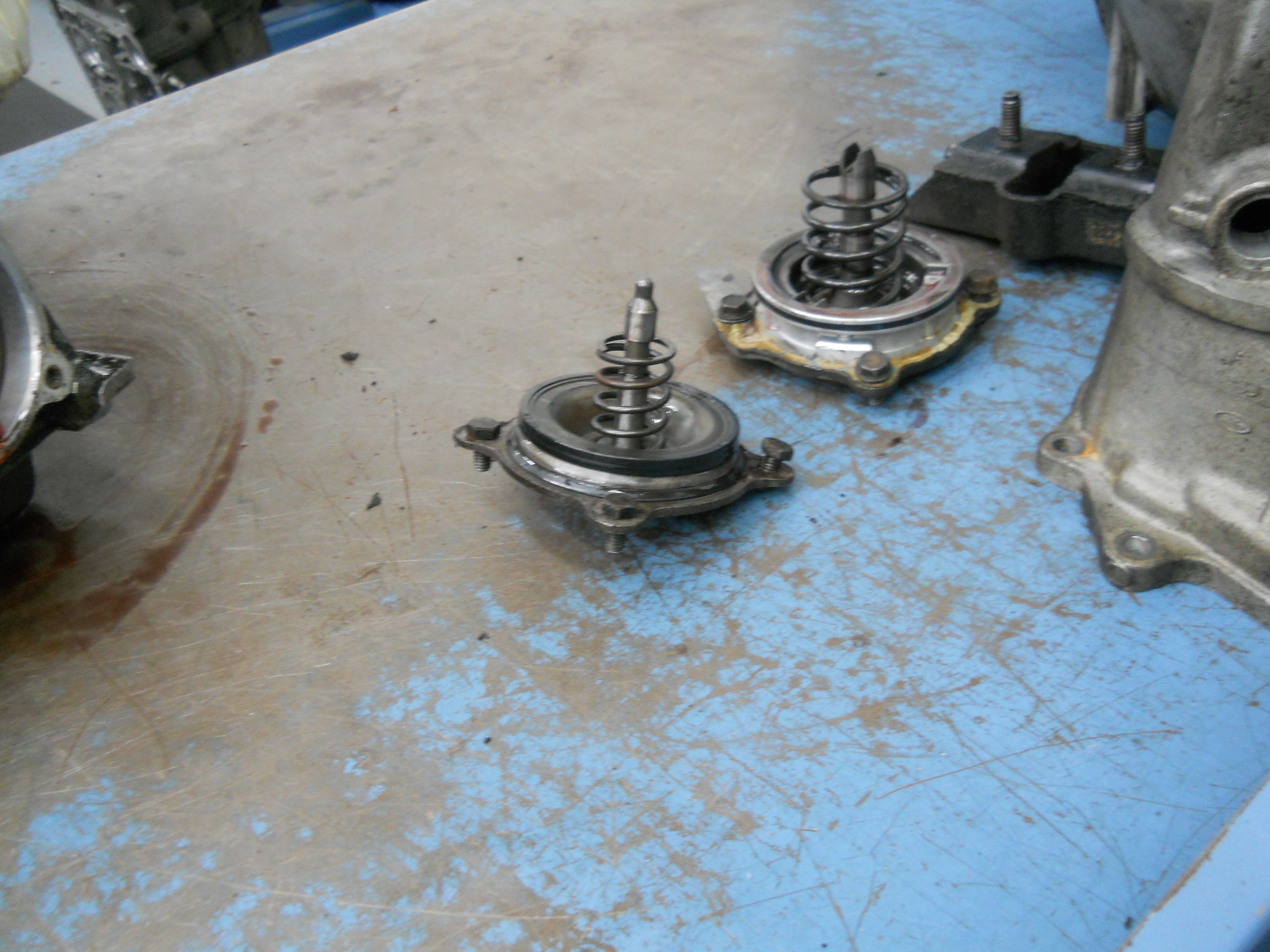 |
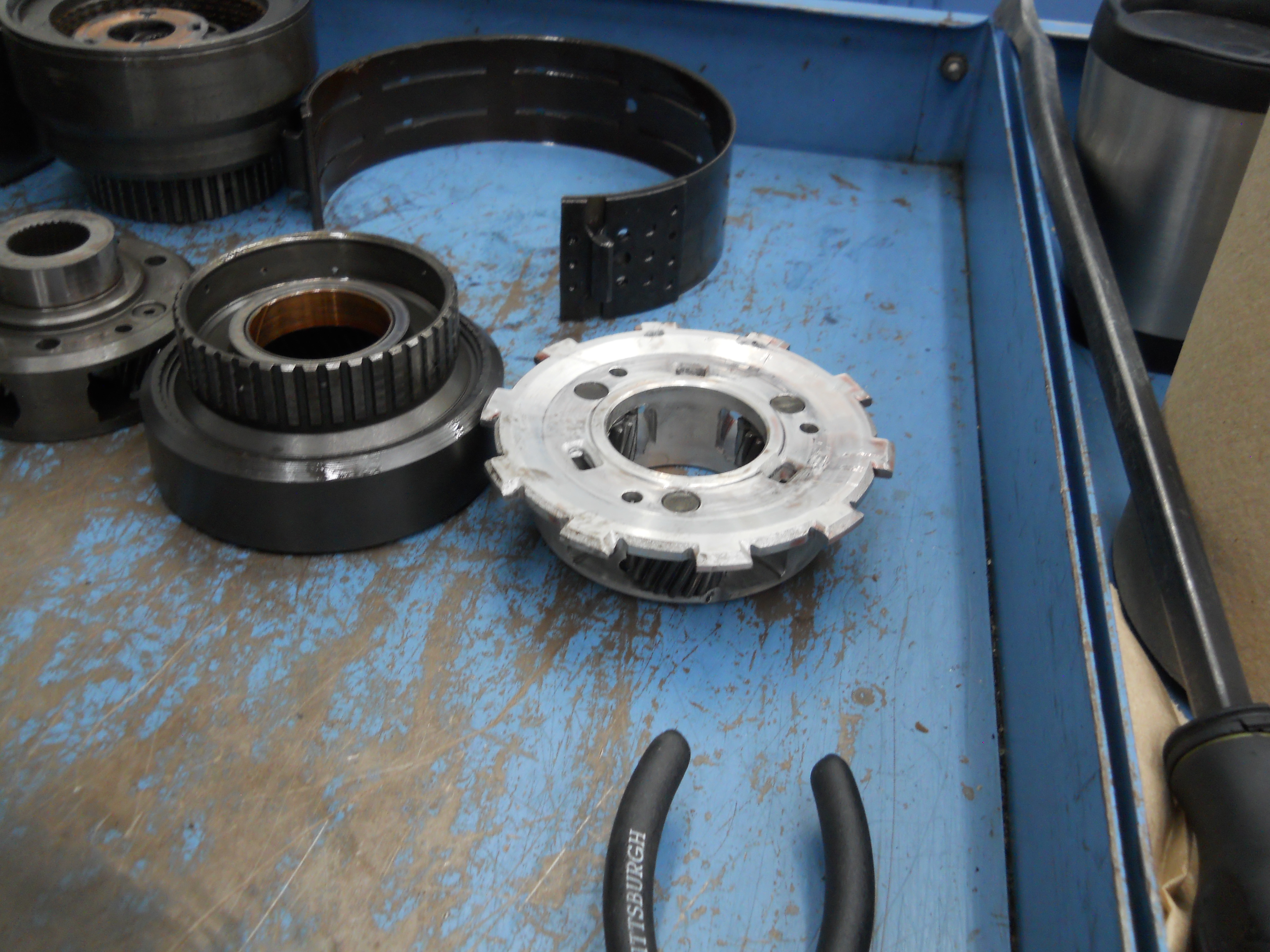
Intermediate Servo and Piston. The "C" coded servo is larger in diameter than the "A" coded servo, 3.13 inches in diameter versus 2.84 inches in diameter which results in greater holding force on the intermediate band.
[C4-DSCN2779] |
Low-Reverse Servo and Piston and Intermediate Servo and Piston after removal from case.
[C4-DSCN2781] |
|
|
|
|
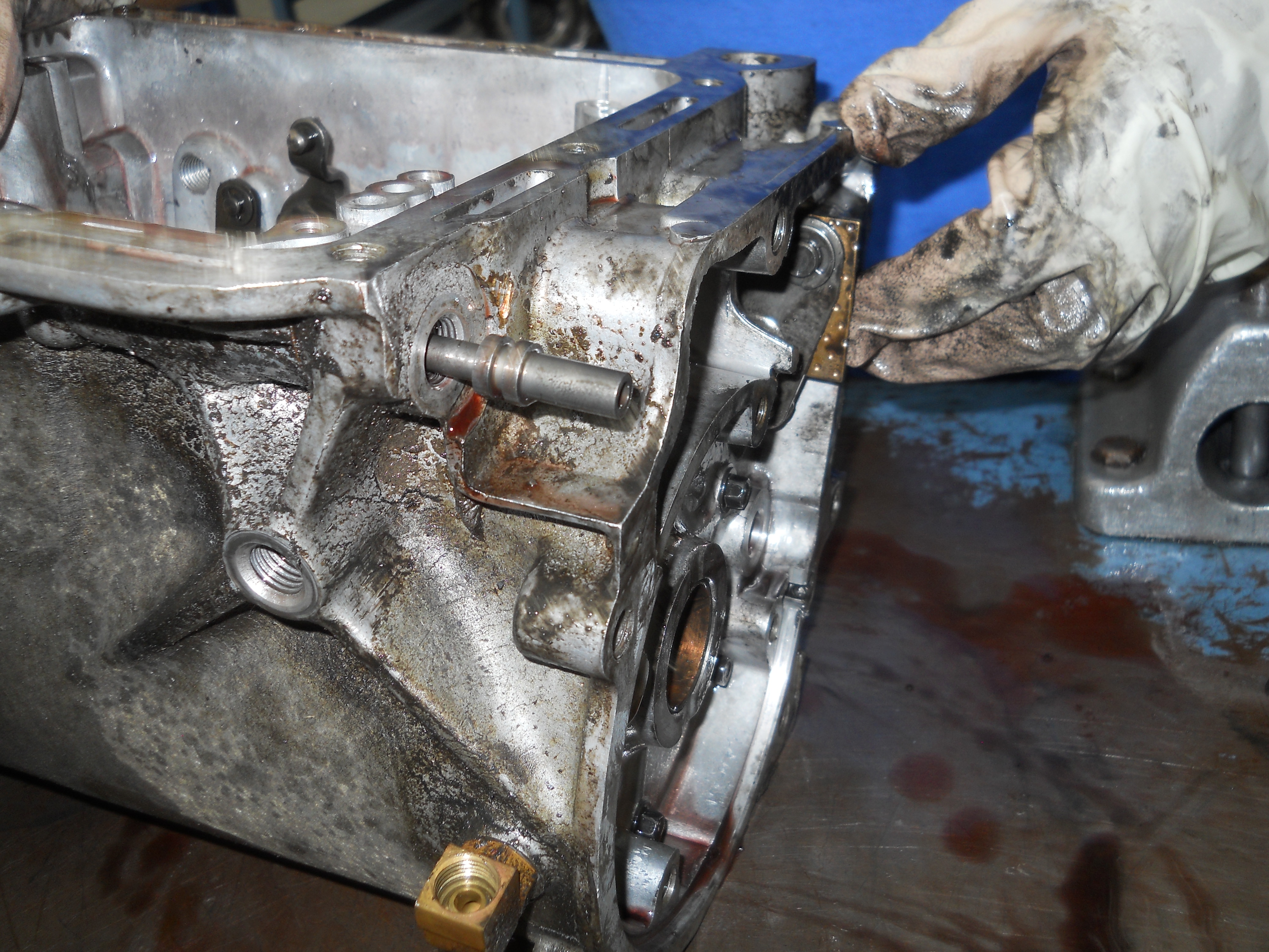
Four bolts hold the governor to the governor distributor. The governor is removed as an assembly.
[C4-DSCN2783] |
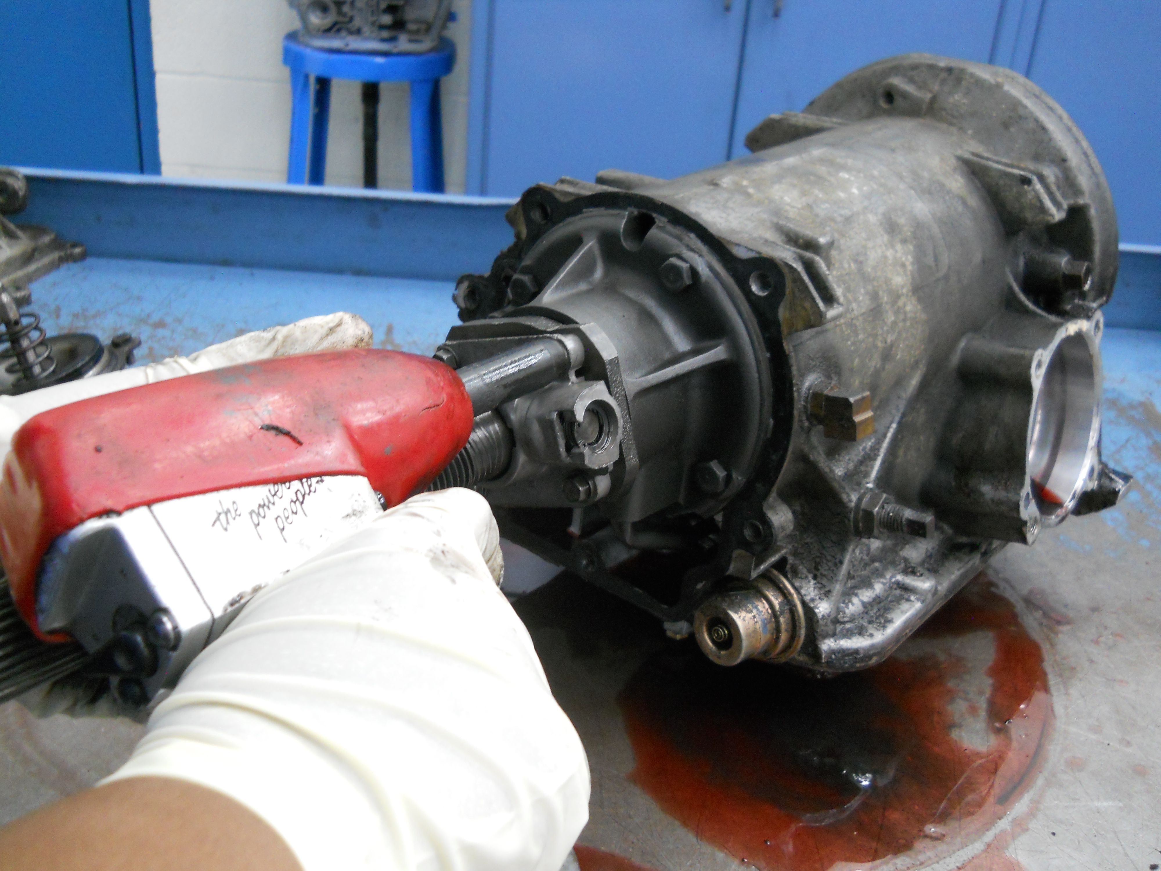
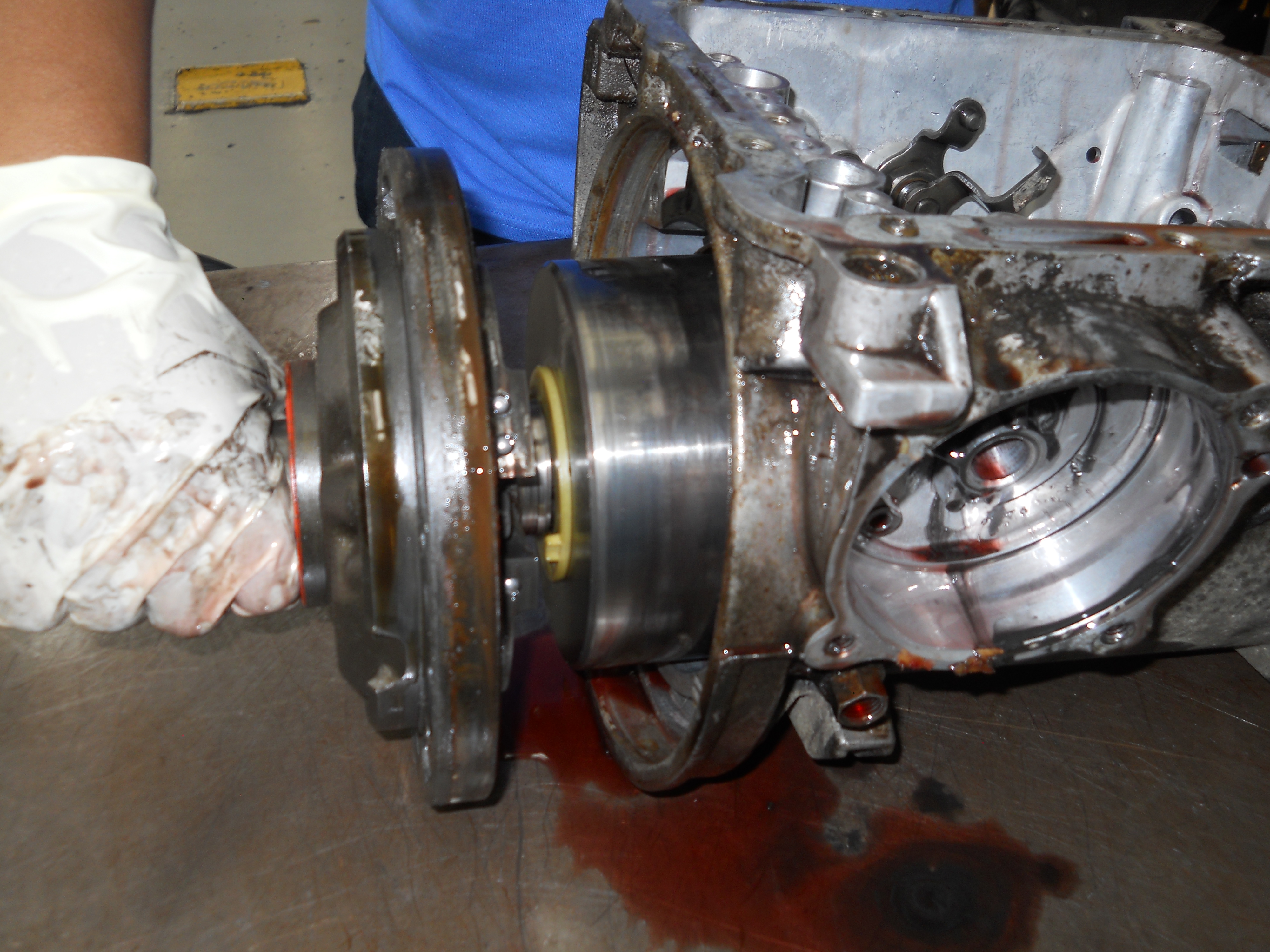
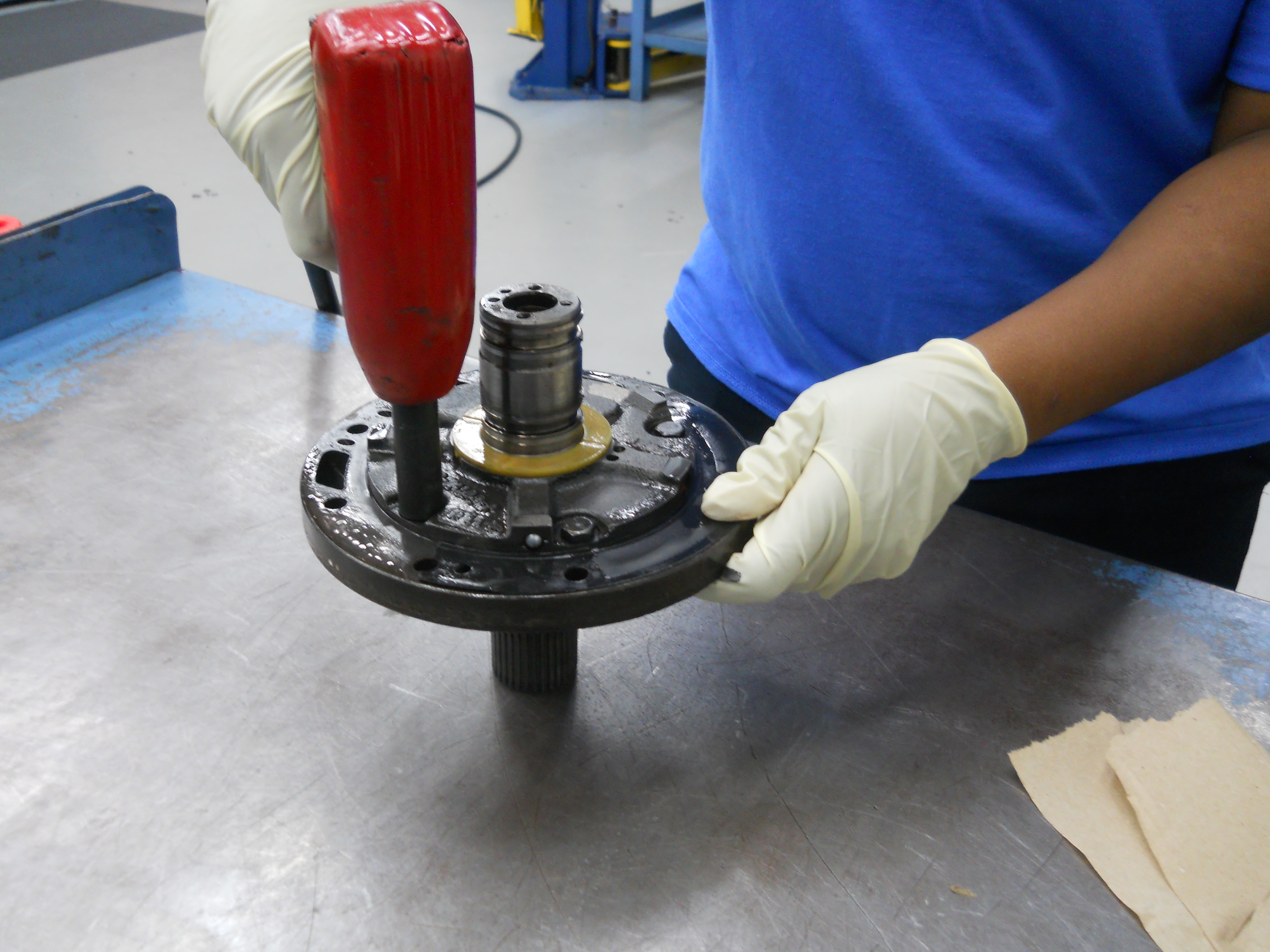
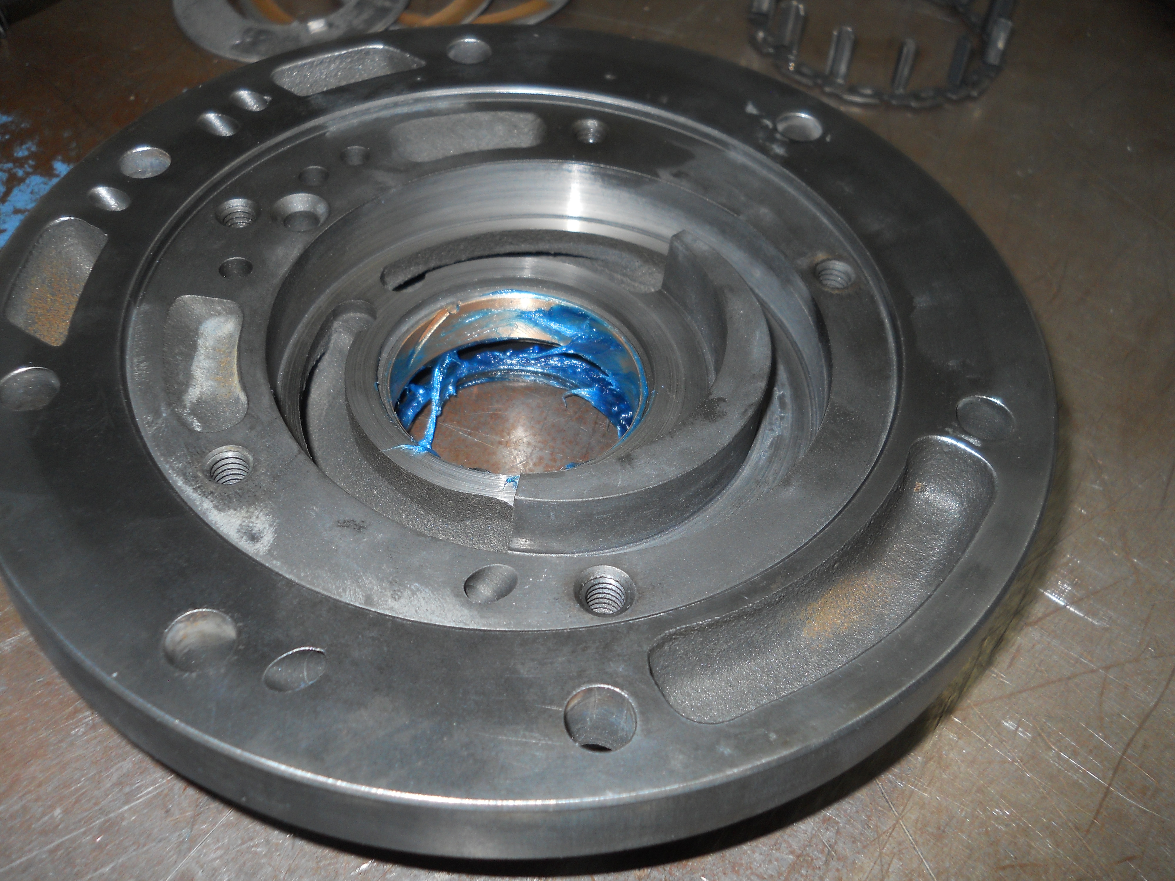
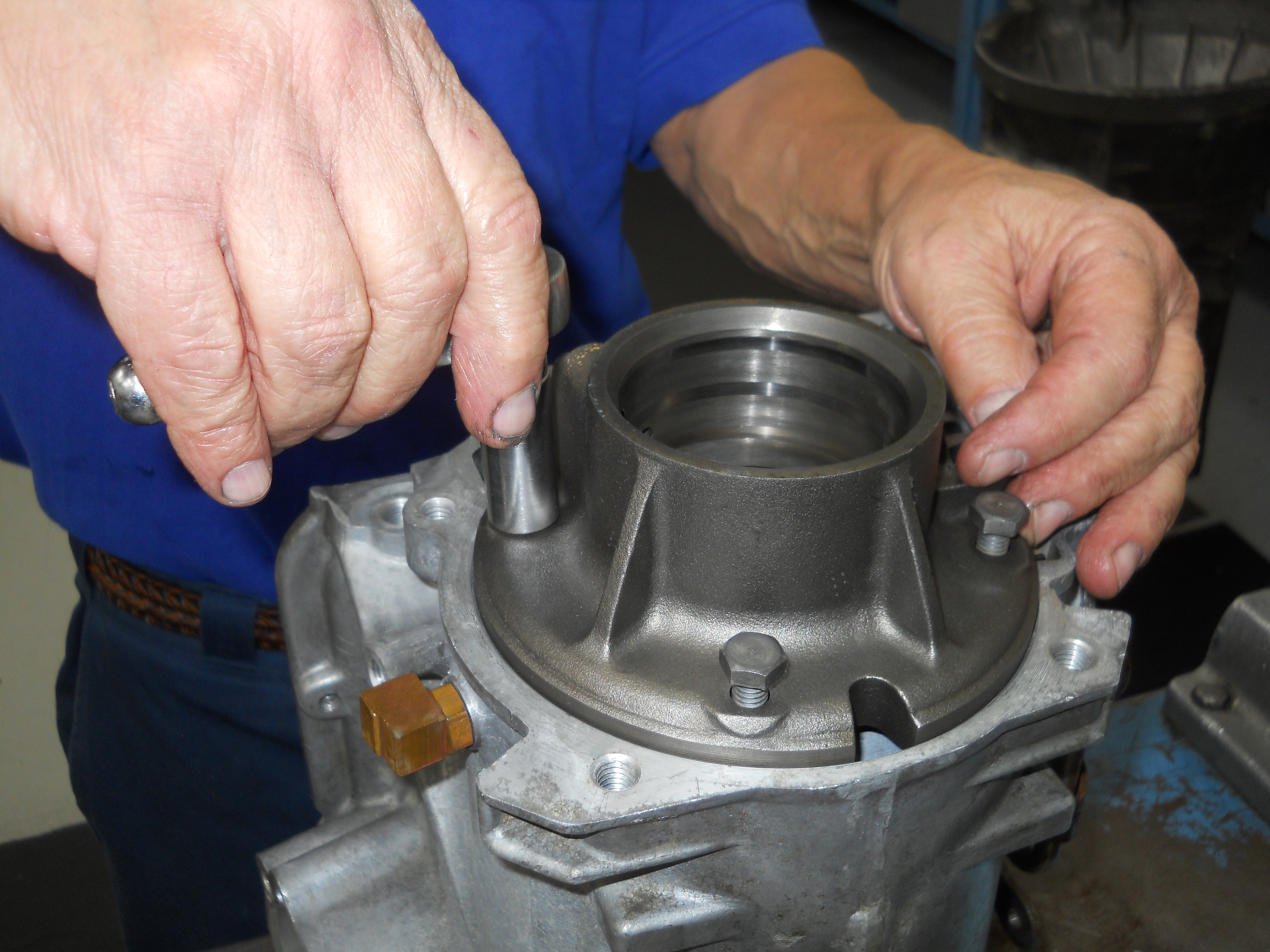
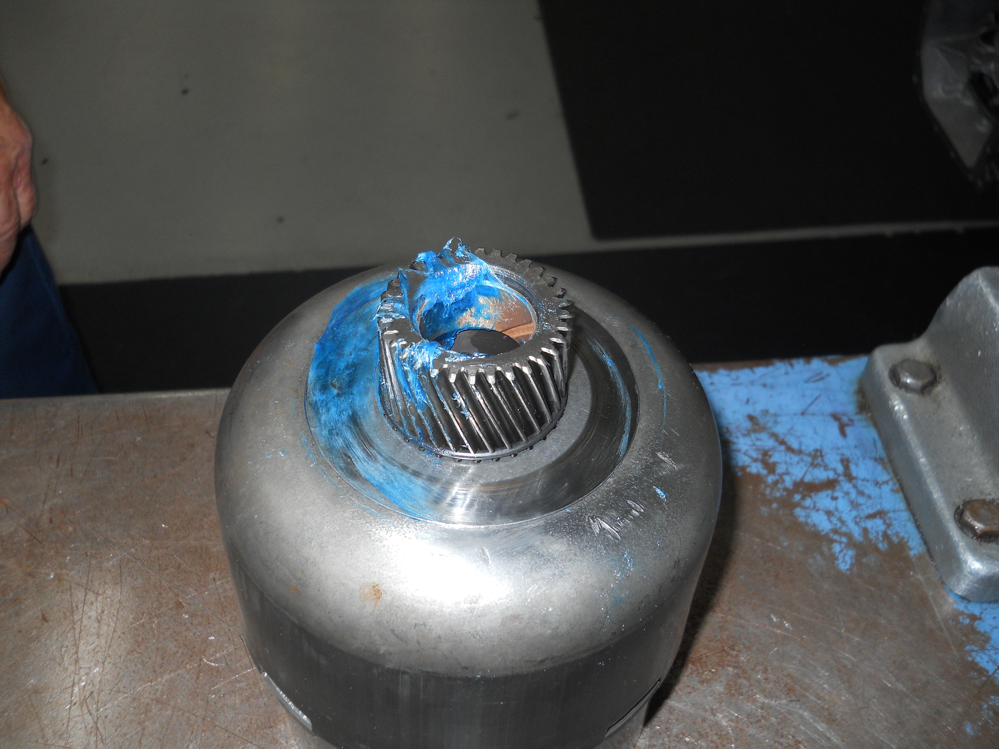
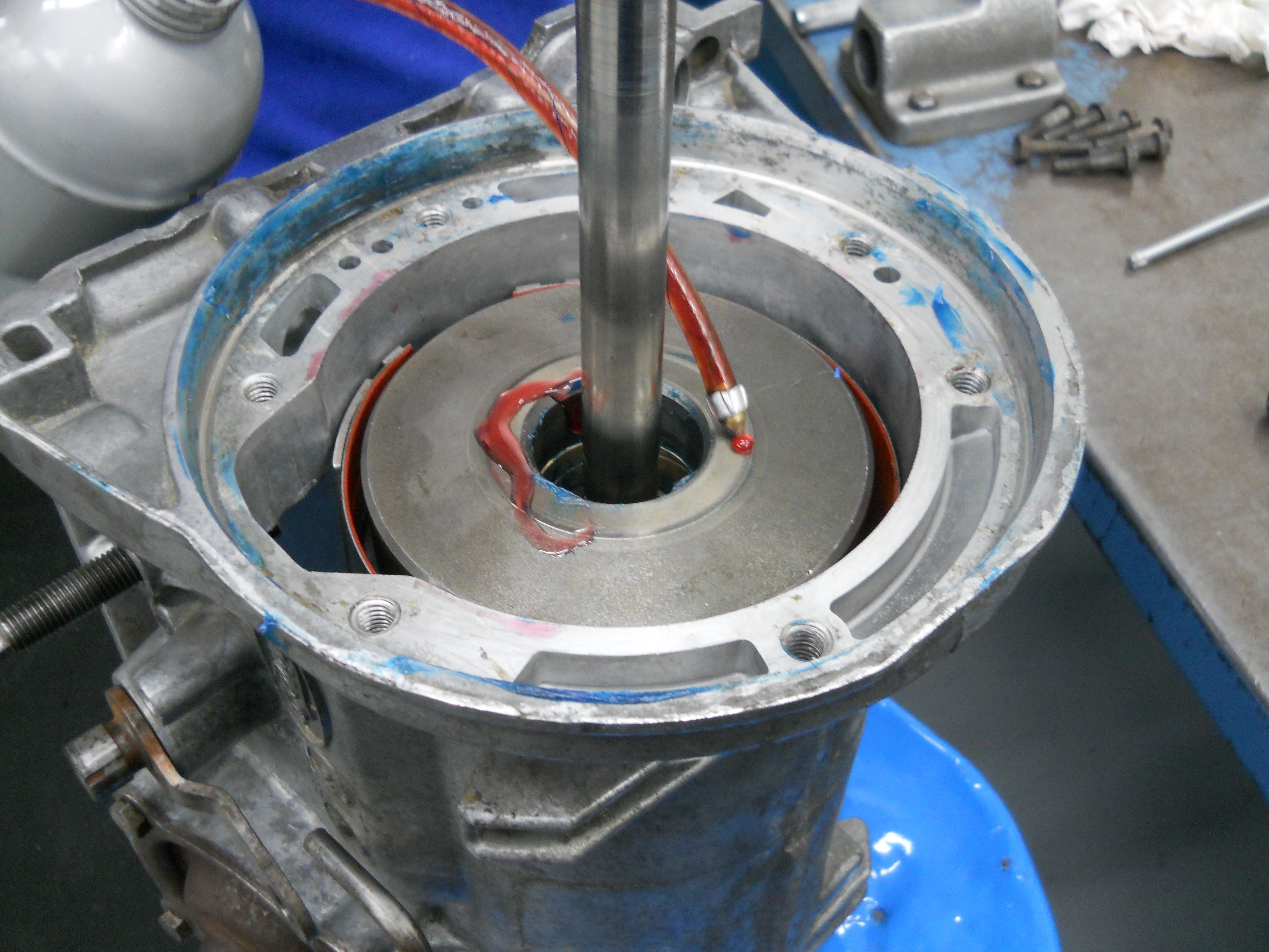
Removing the front pump. It is best to remove the pump with a tool specifically designed for that purpose, otherwise there is a risk of breaking the pump assembly by using impact tools. Hammer mechanics take note.
[C4-DSCN2785] |
|
|
|
|
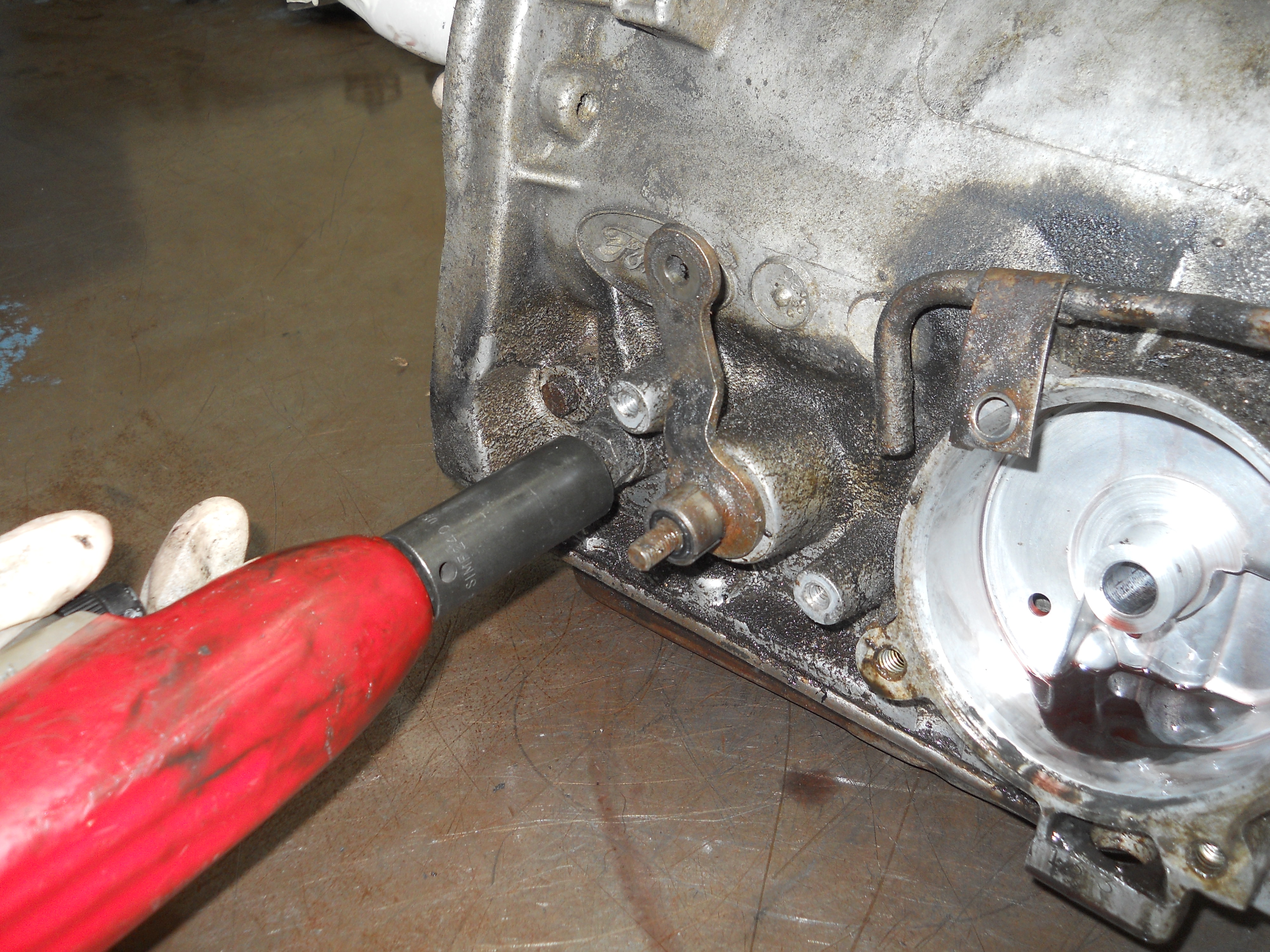
Removing the Intermediate Band Adjuster.
[C4-DSCN2786] |
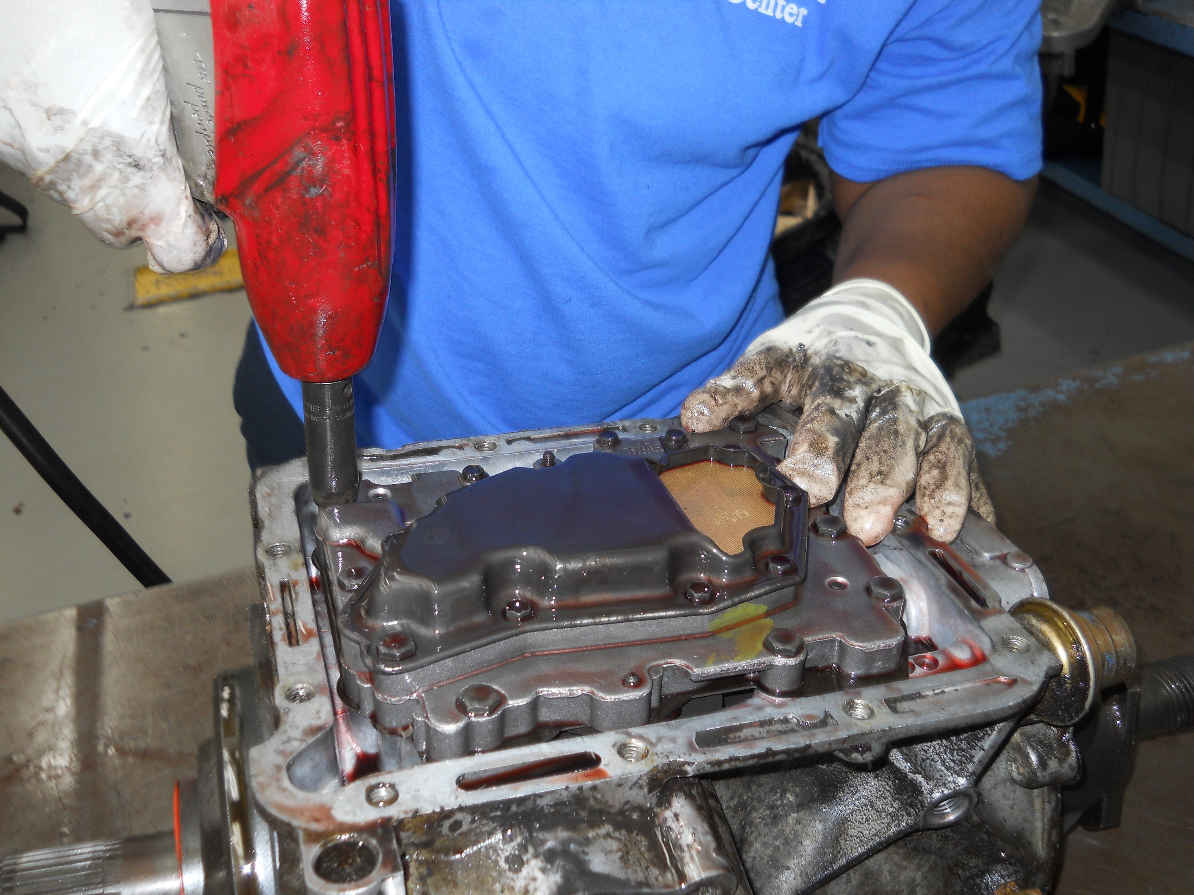
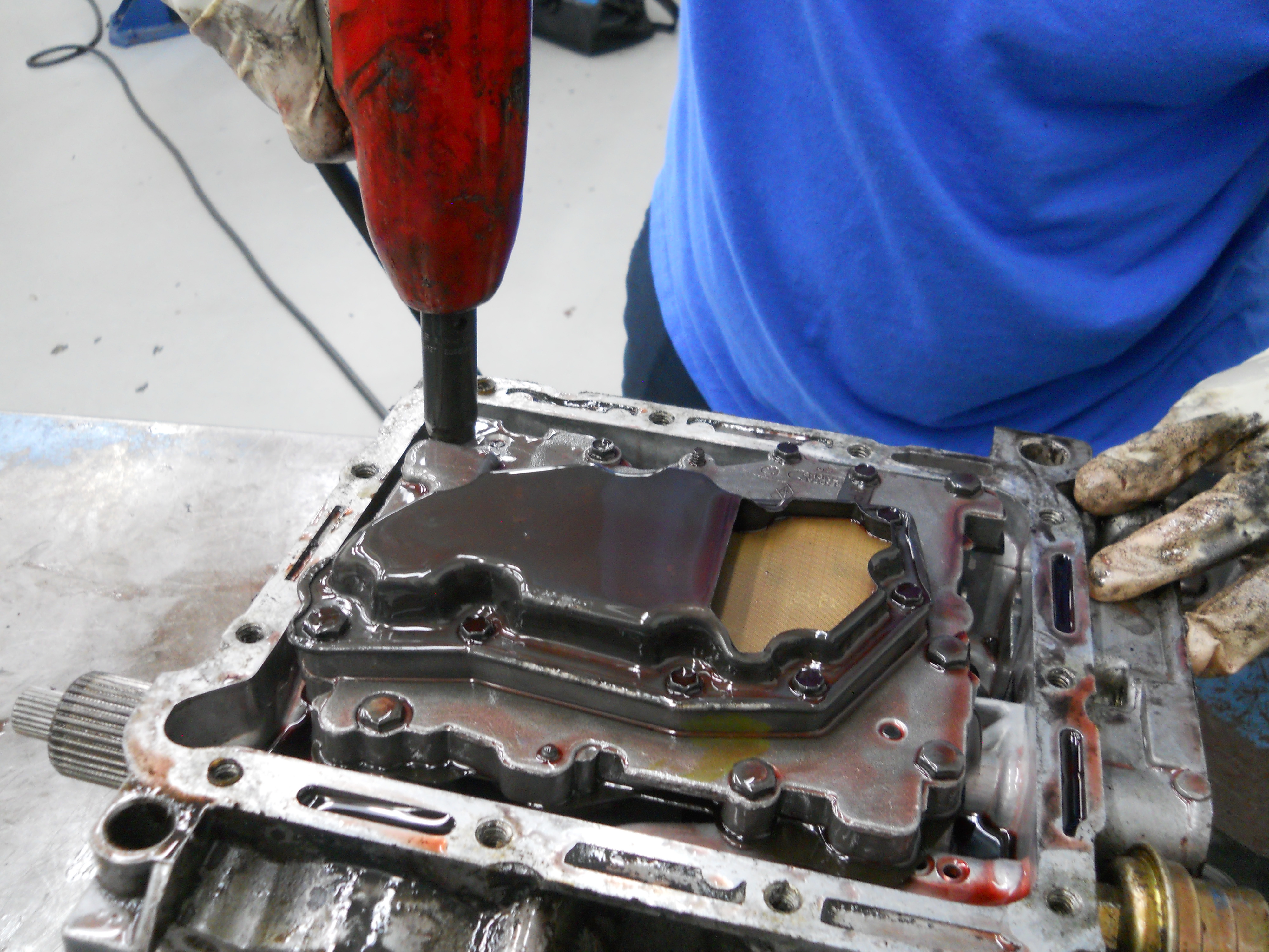
Oil Pan Removal. Oil pan is held to the case by 11 bolts.
[C4-DSCN2788] |
|
|
|
|
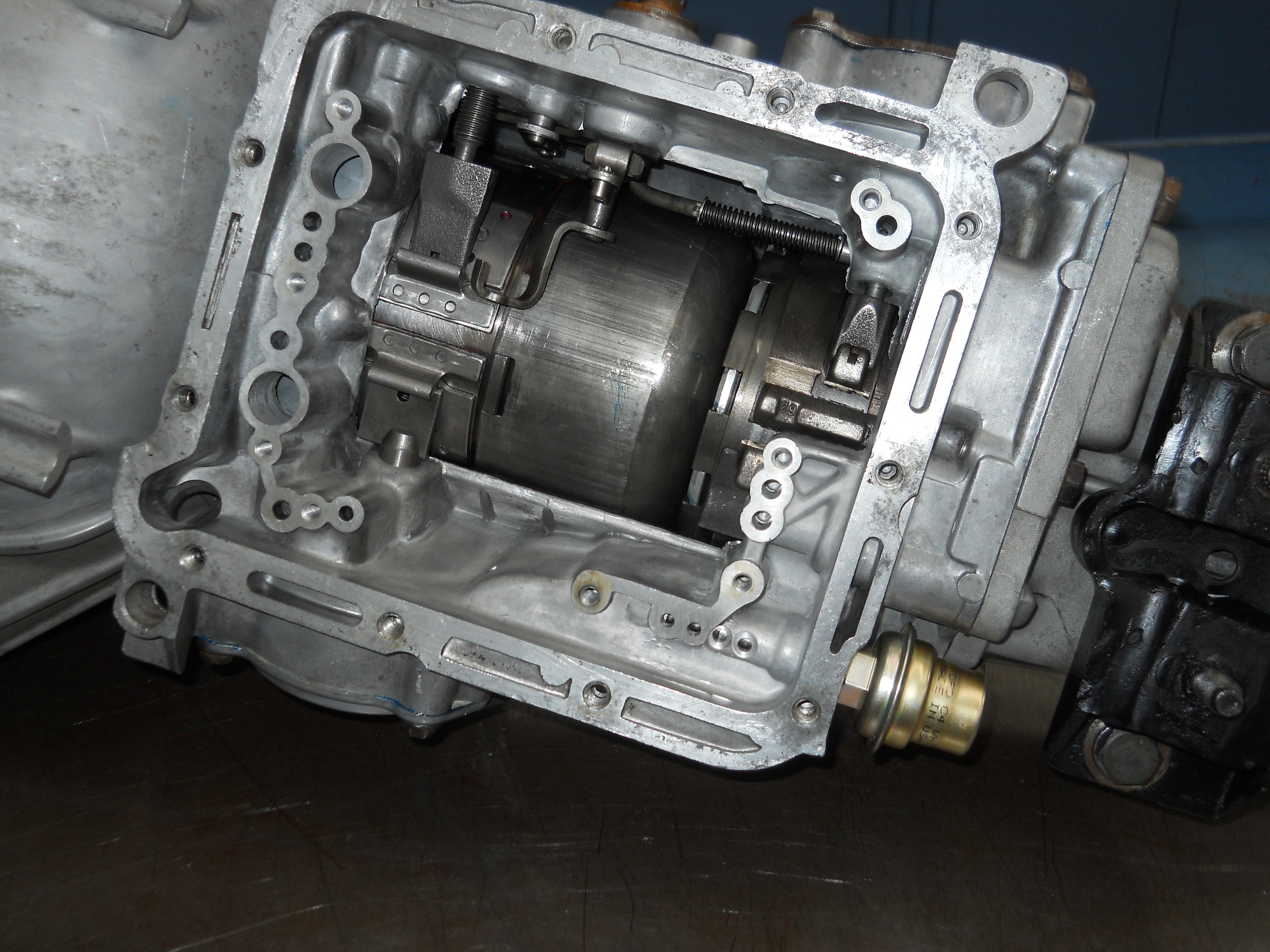
Valve Body removal. Valve Body is held on by 8 bolts. Other valve bodies use 9 bolts.
[C4-DSCN2789] |
A separate set of bolts hold the filter and screeen to the valve body.
[C4-DSCN2790] |
|
|
|
|
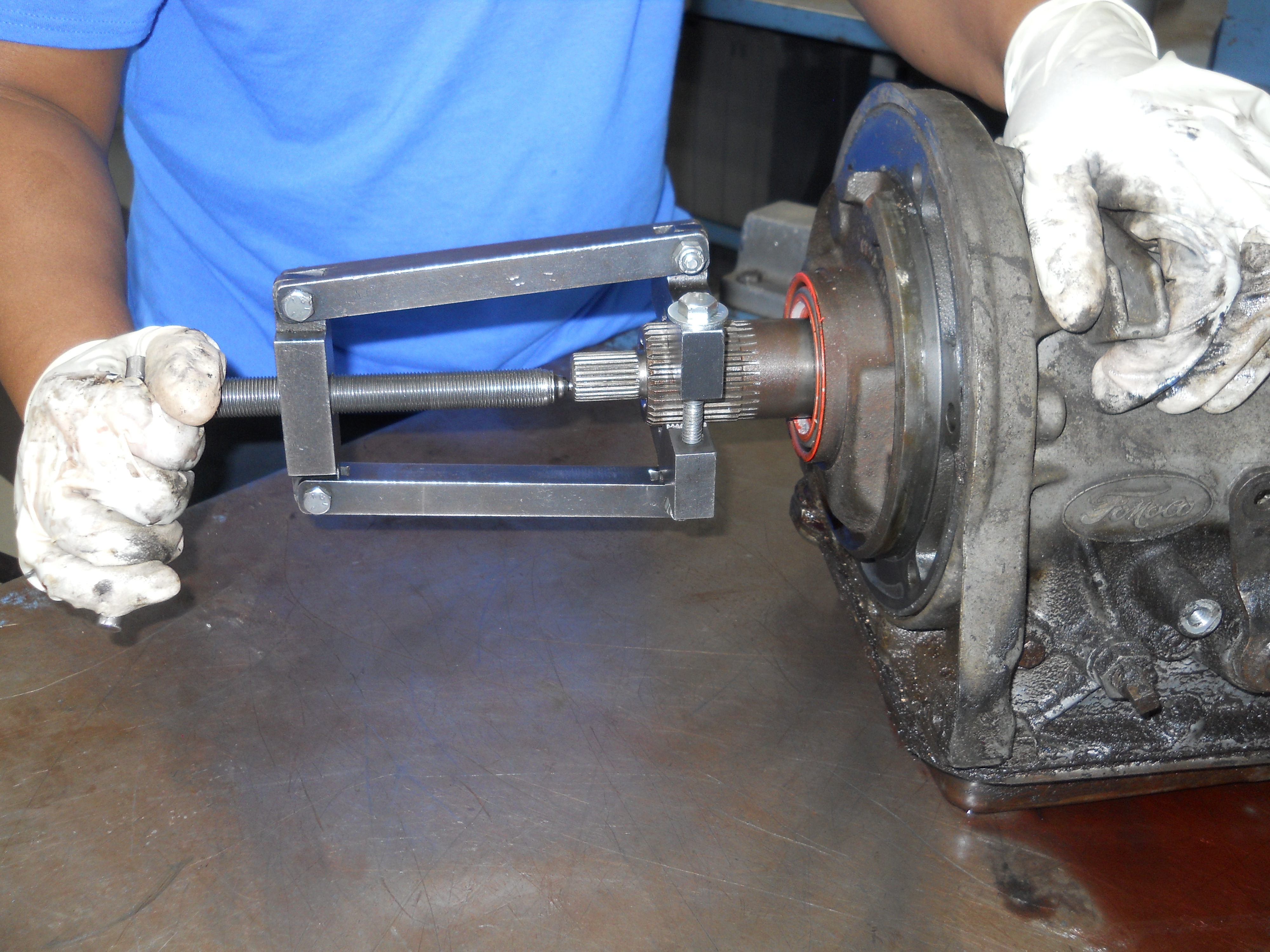
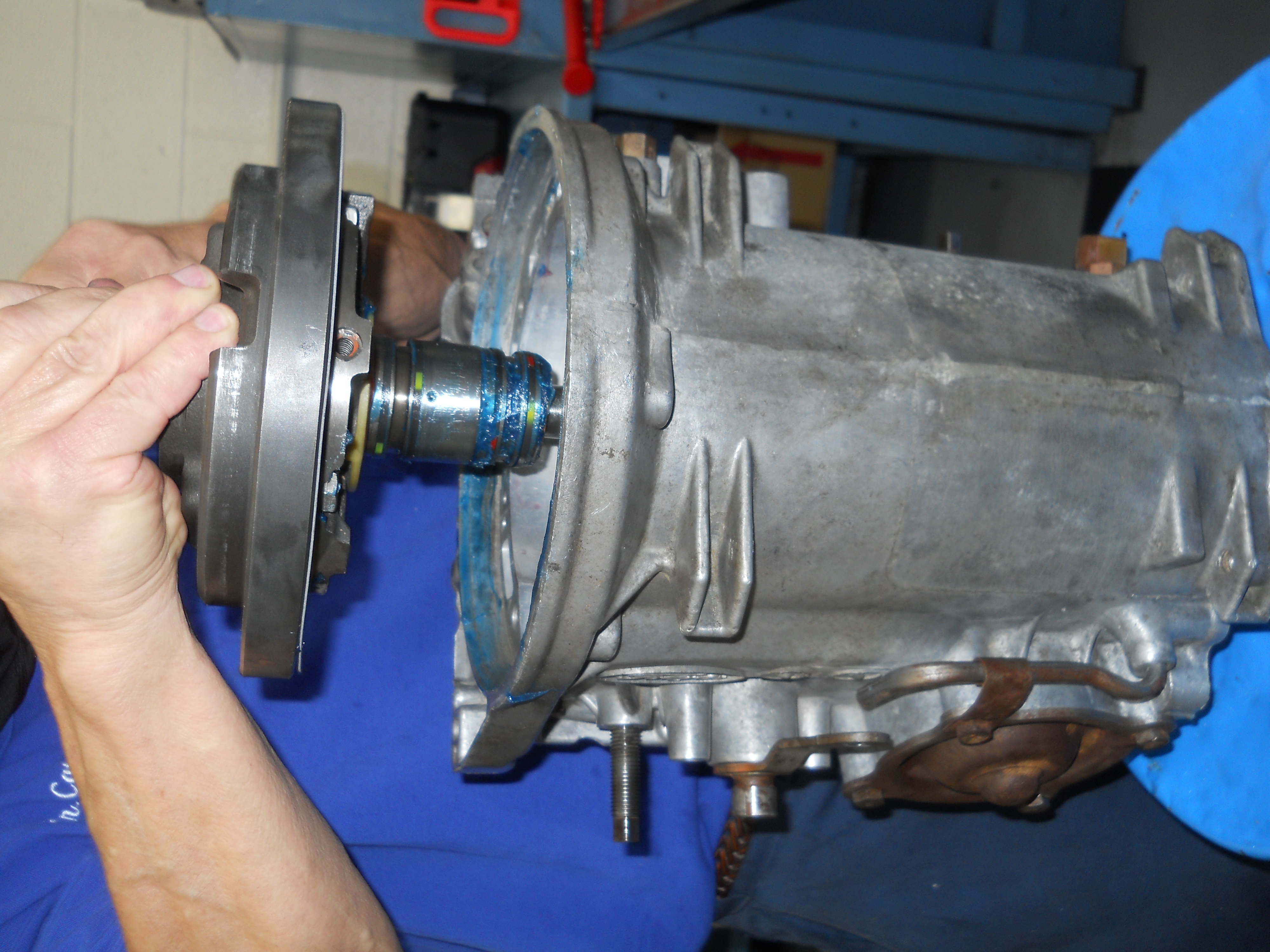
Removing the Front Pump from the transmission case.
[C4-DSCN2791] |
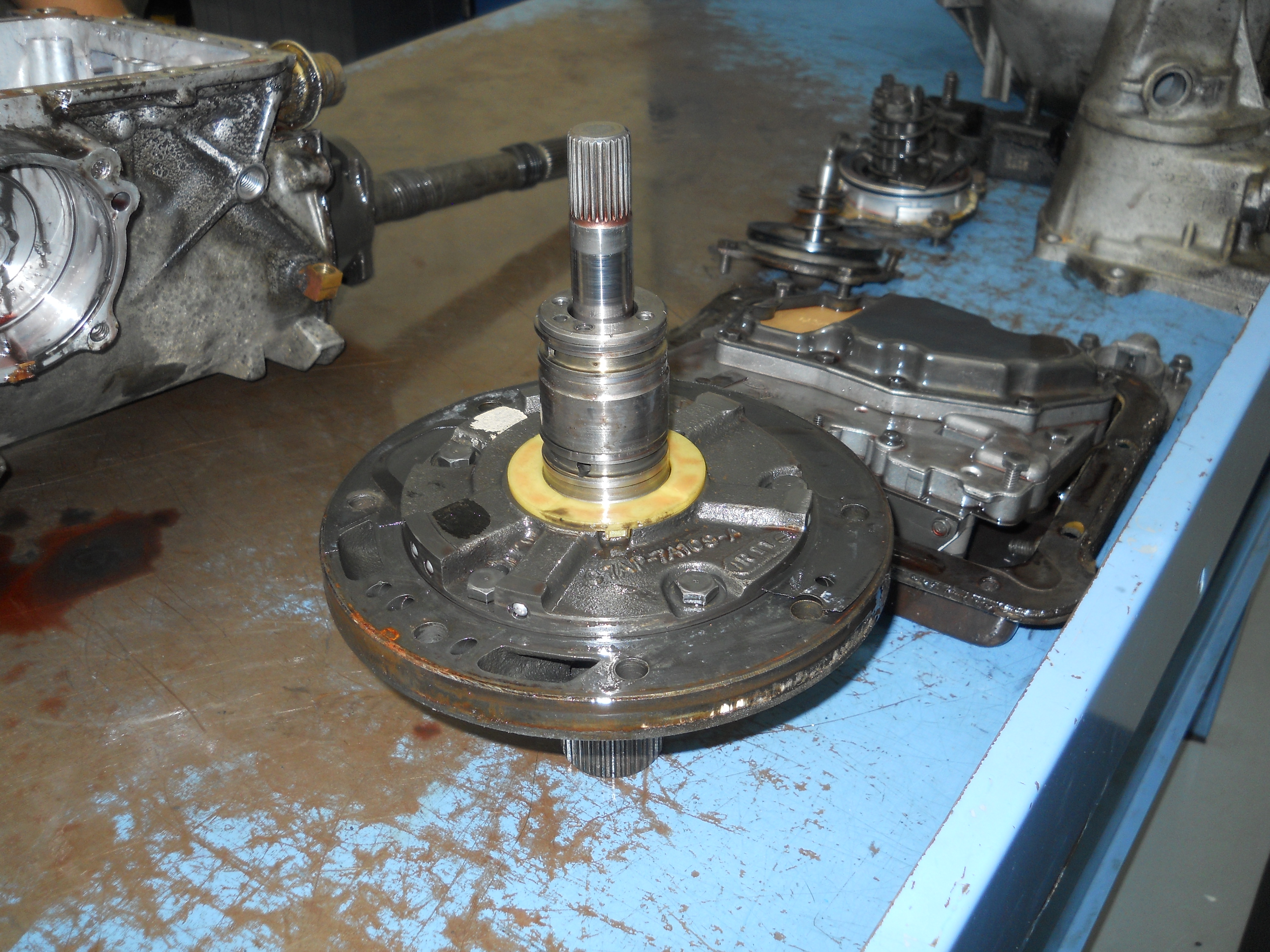
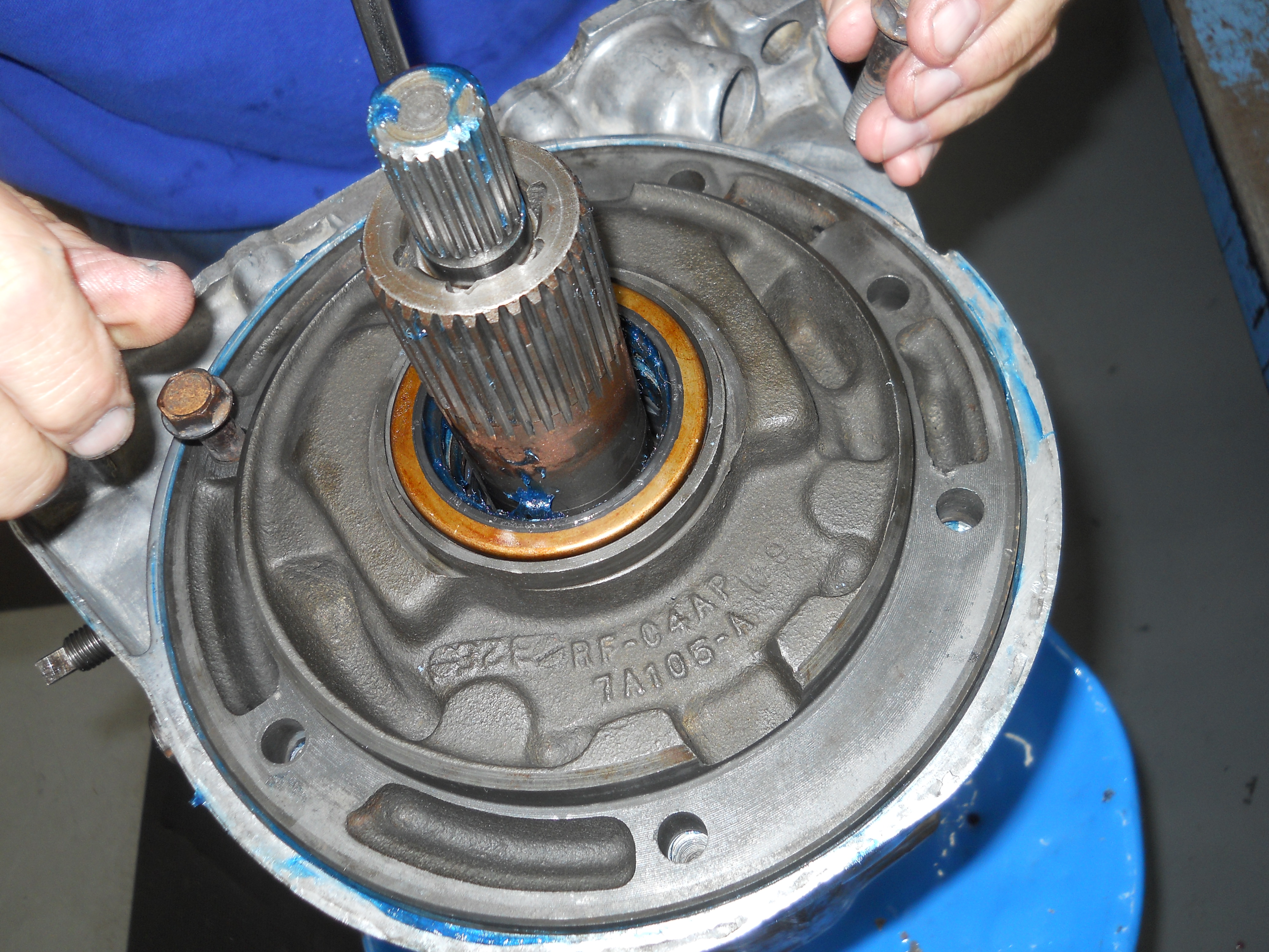
Front Pump with Input Shaft and Valve Body on the bench.
[C4-DSCN2792] |
|
|
|
|
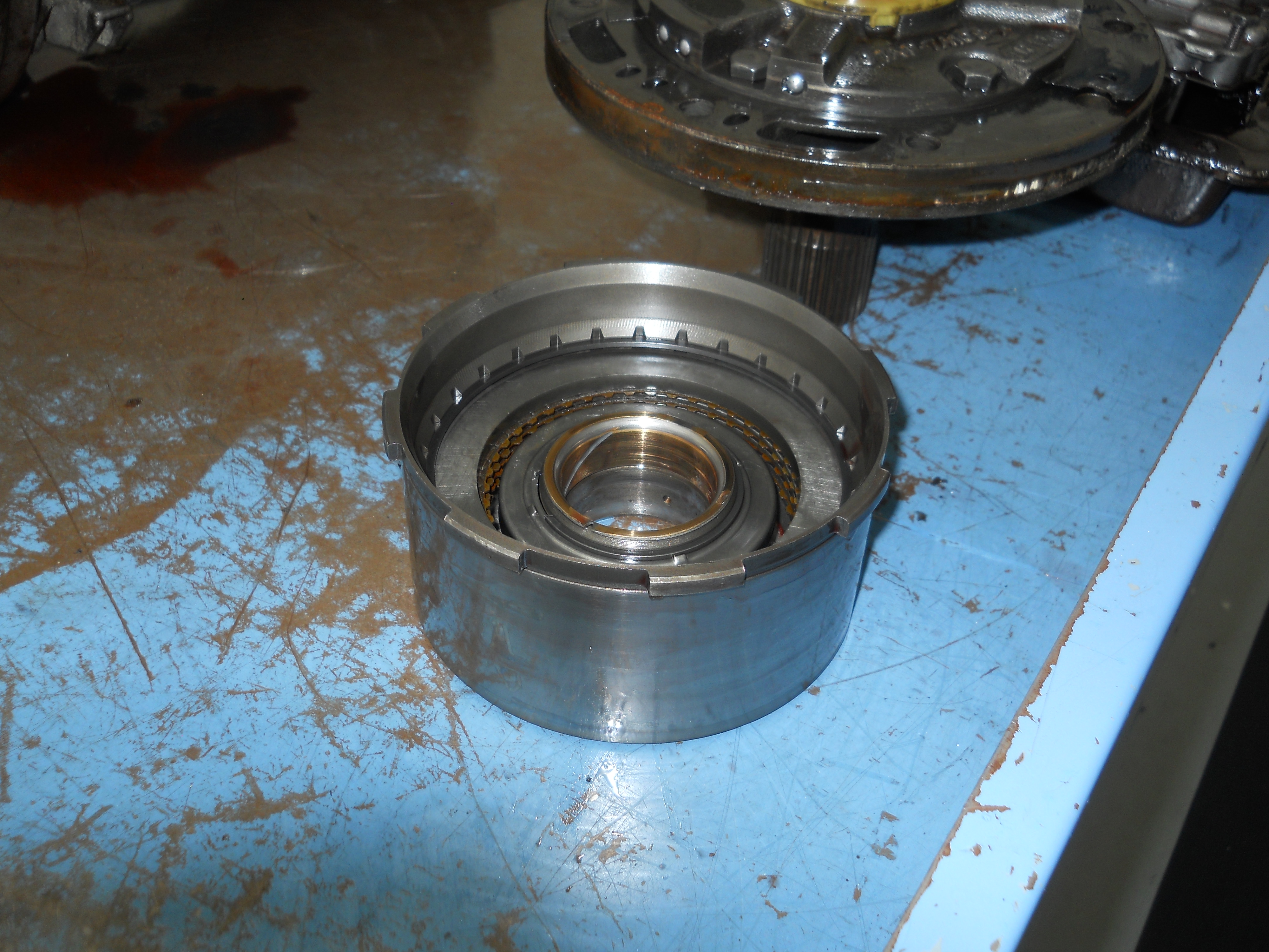
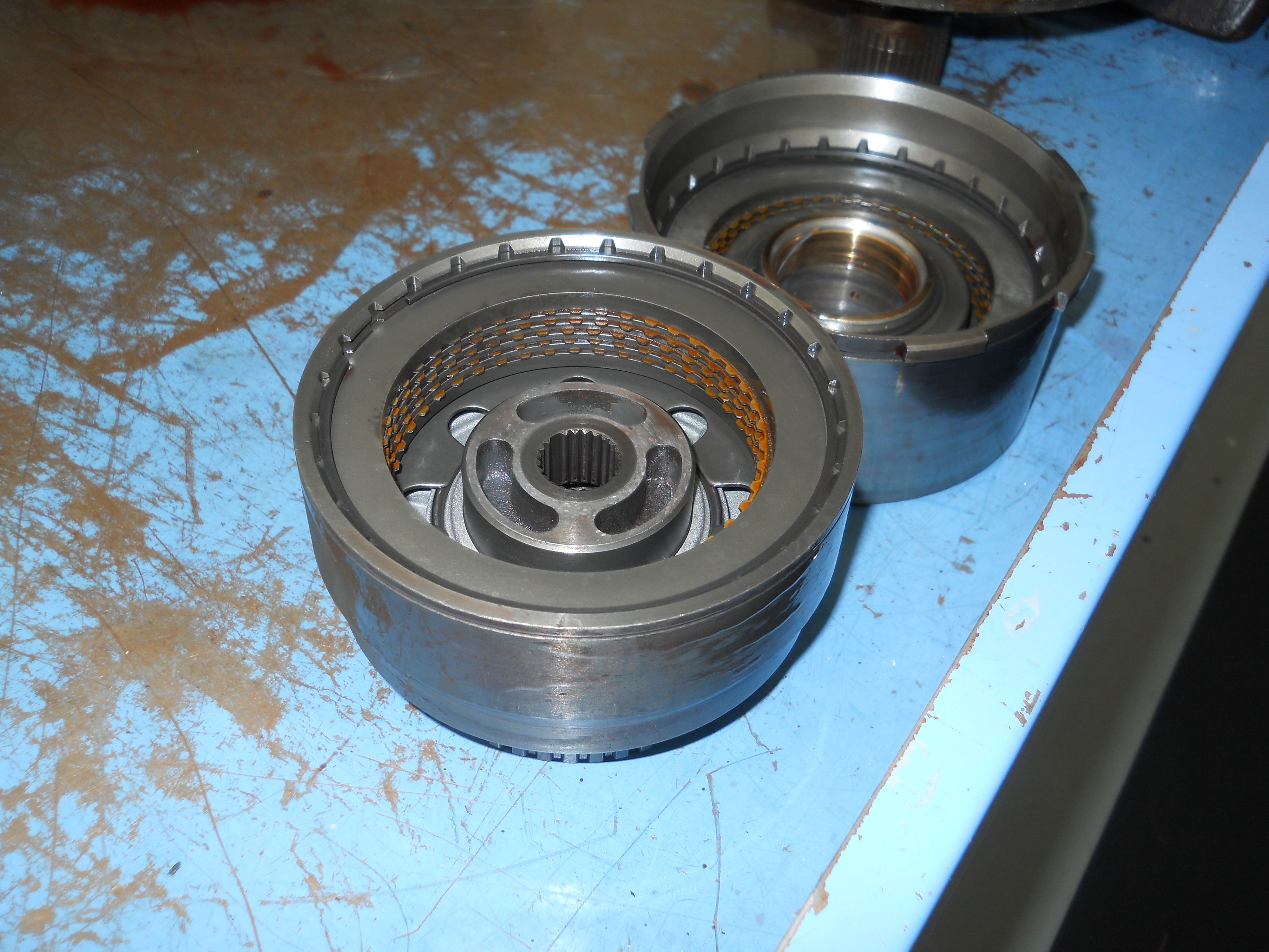
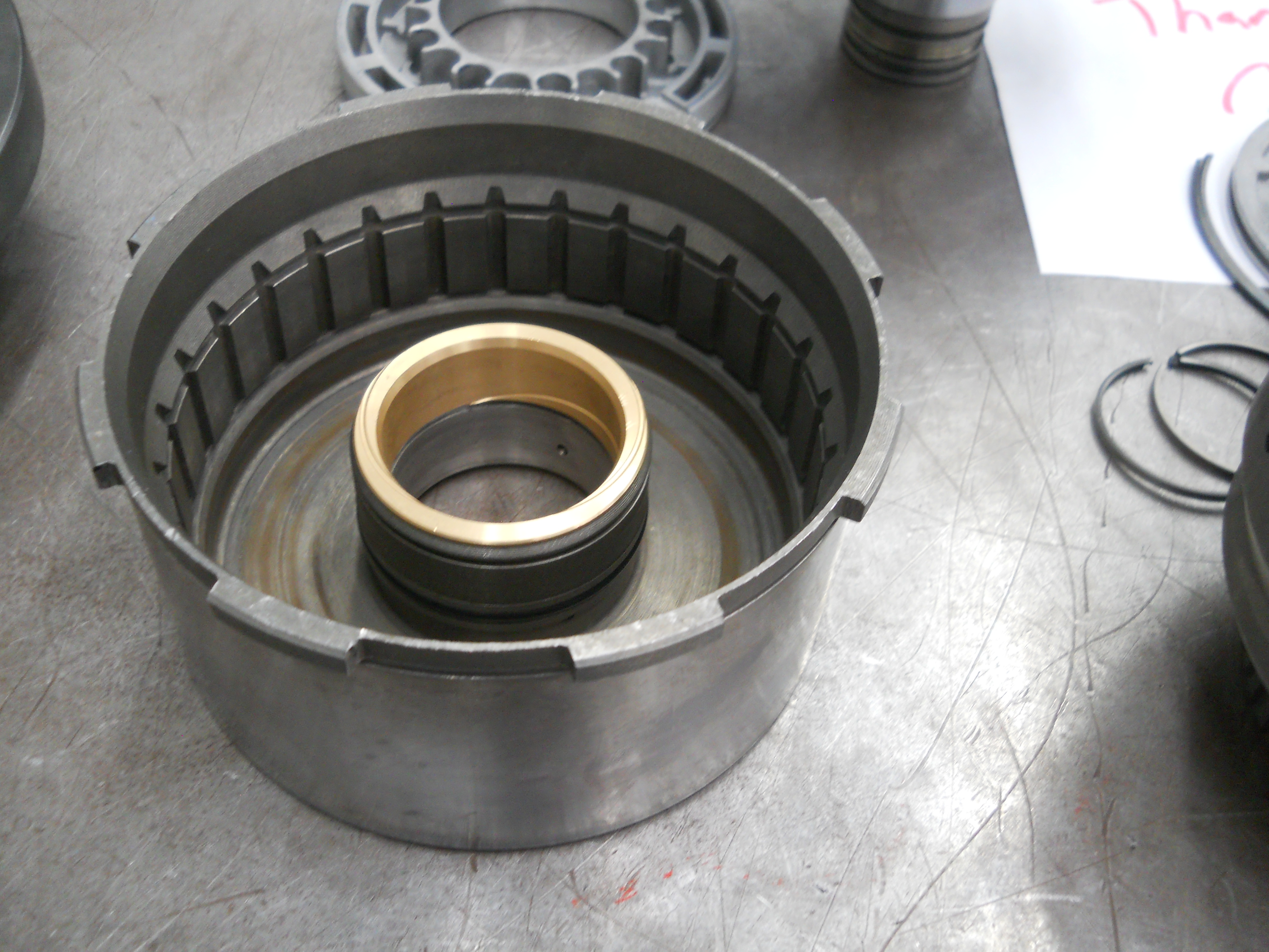
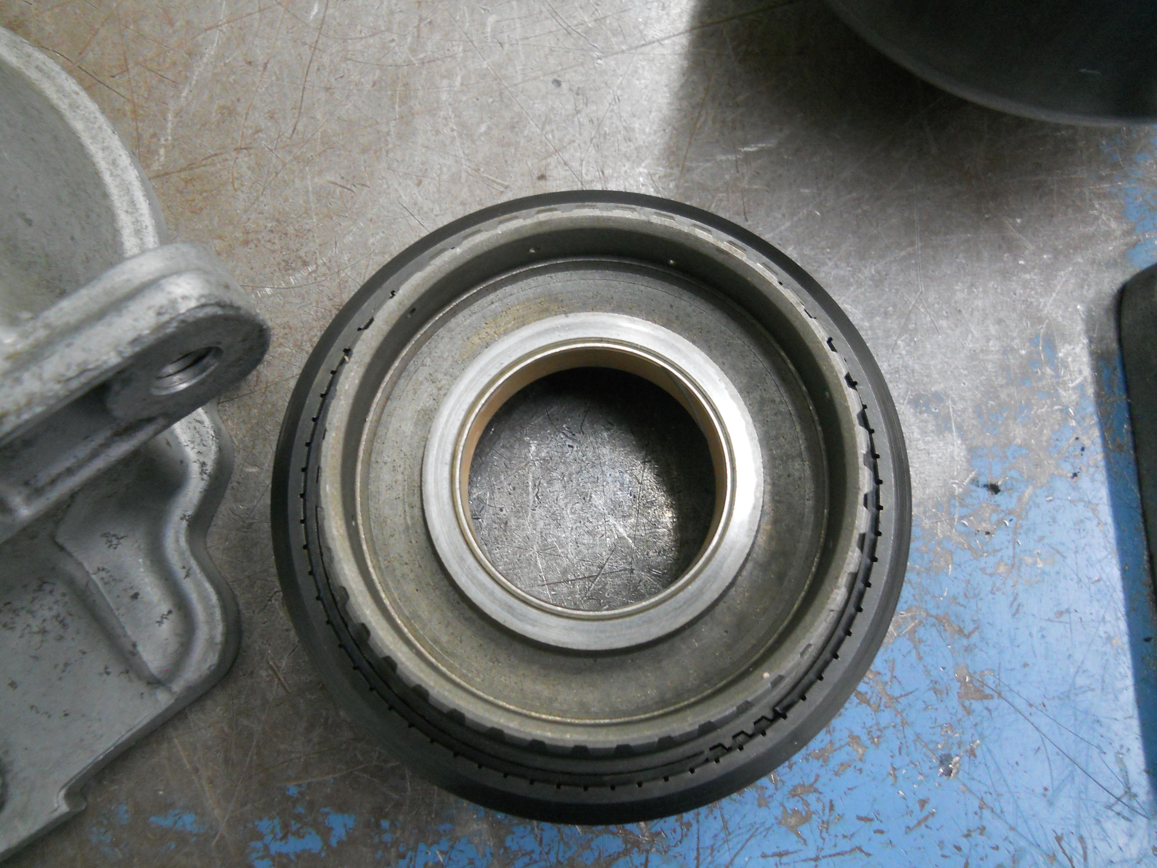
Direct clutch drum for 3rd gear and reverse.
[C4-DSCN2793] |
Forward clutch drum used in all forward ranges and 1st, 2nd and 3rd gears.
[C4-DSCN2794] |
|
|
|
|
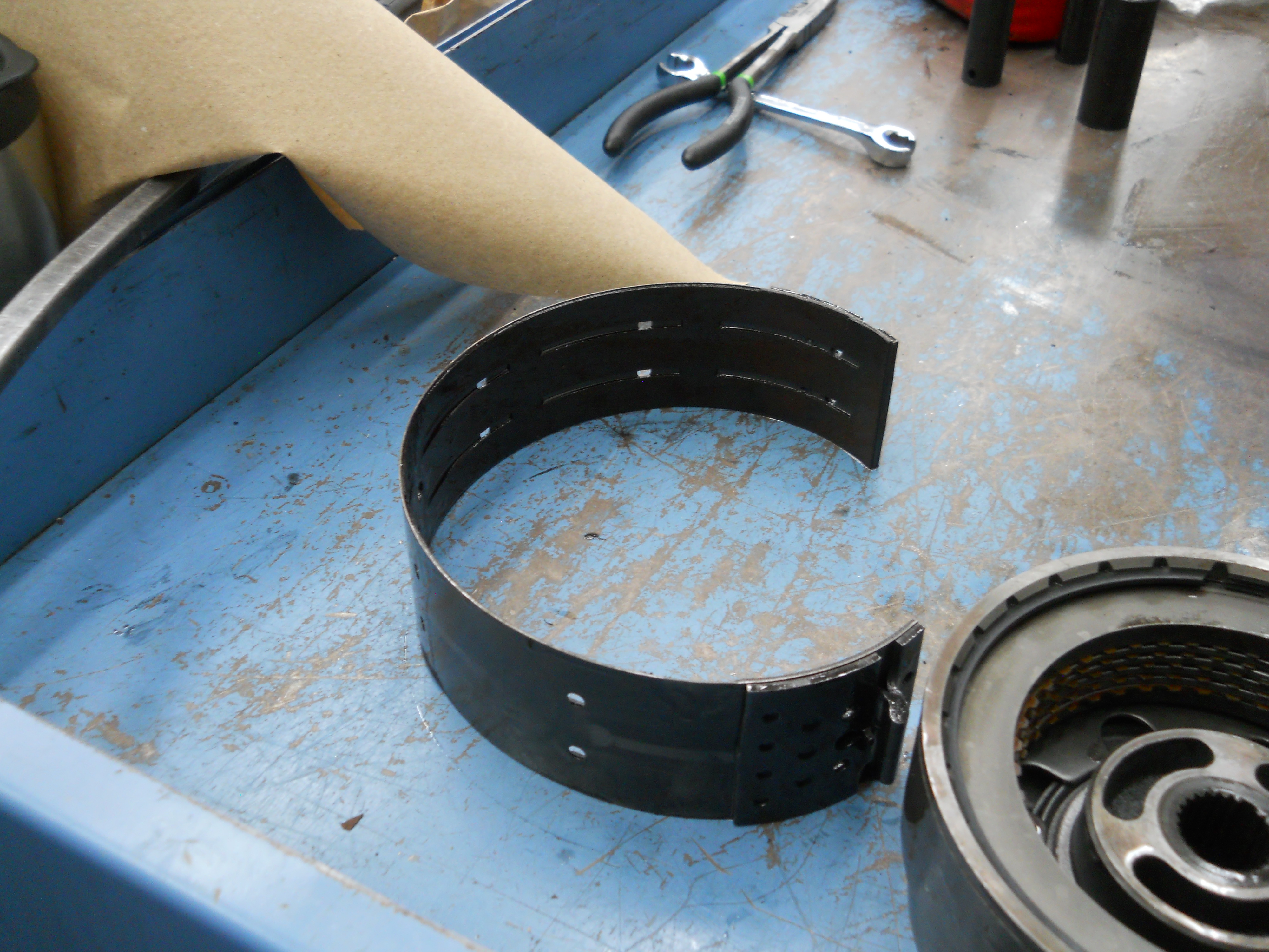
2nd gear band. Ford calls this the intermediate band.
[C4-DSCN2795] |
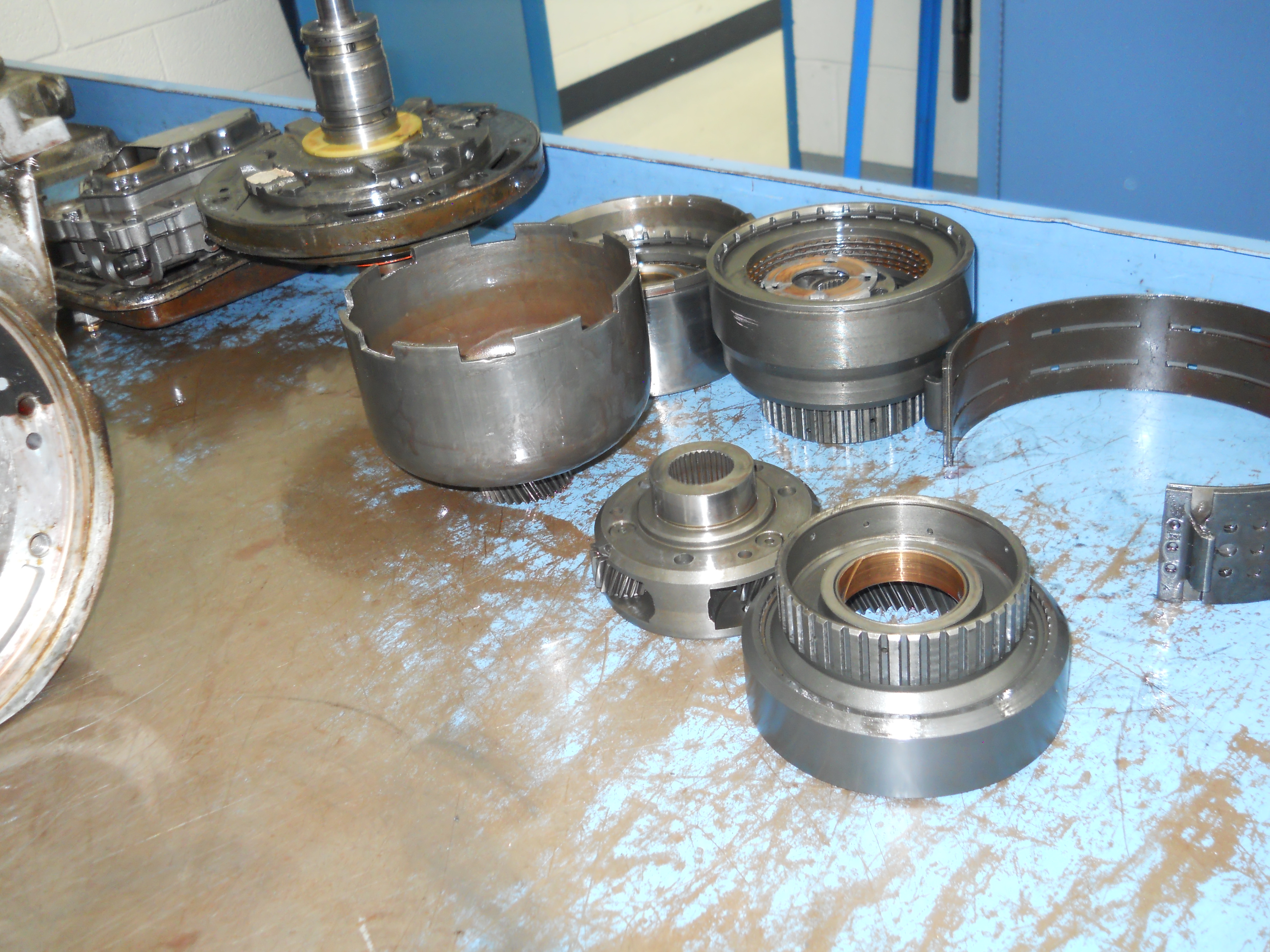
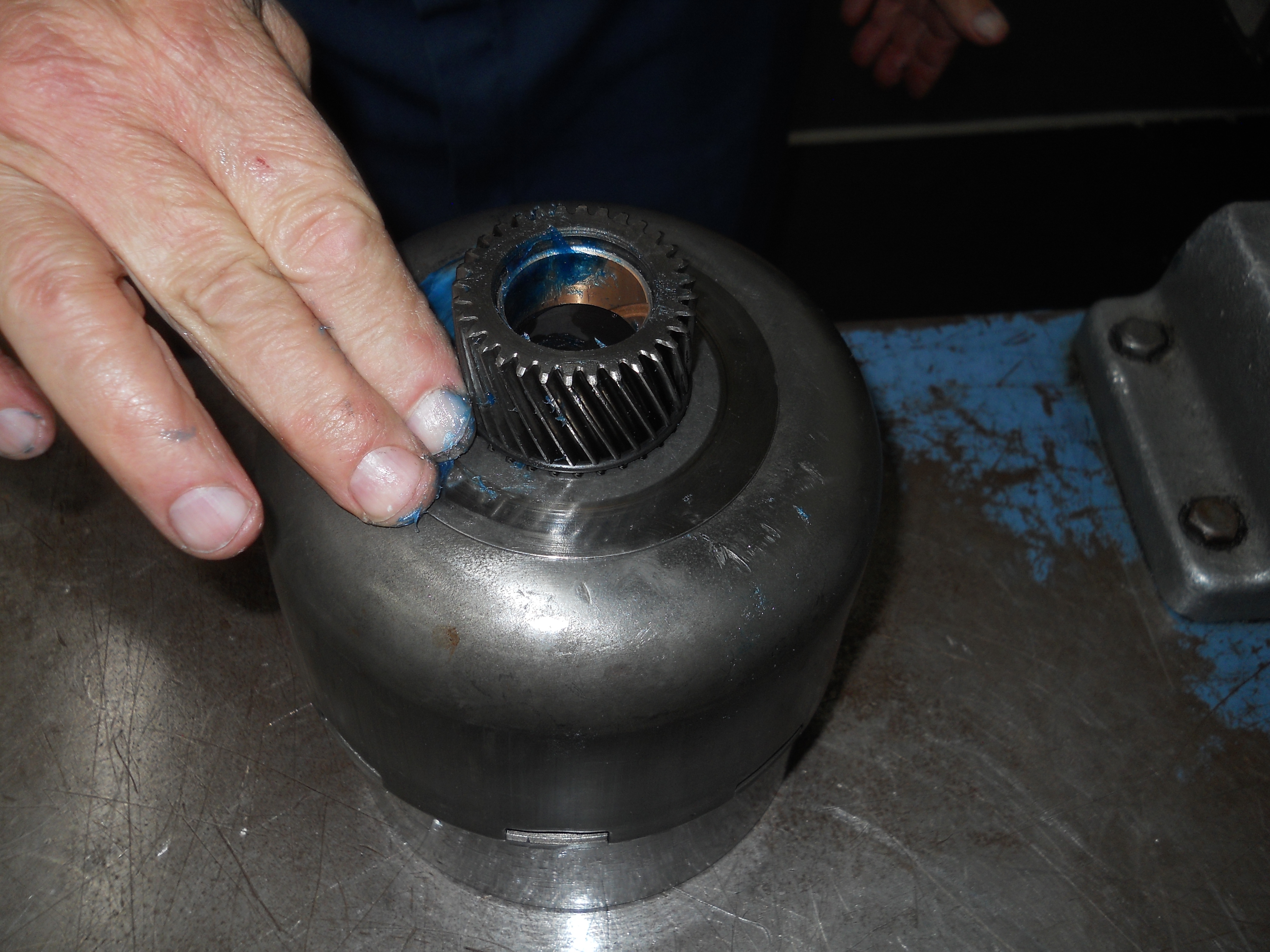
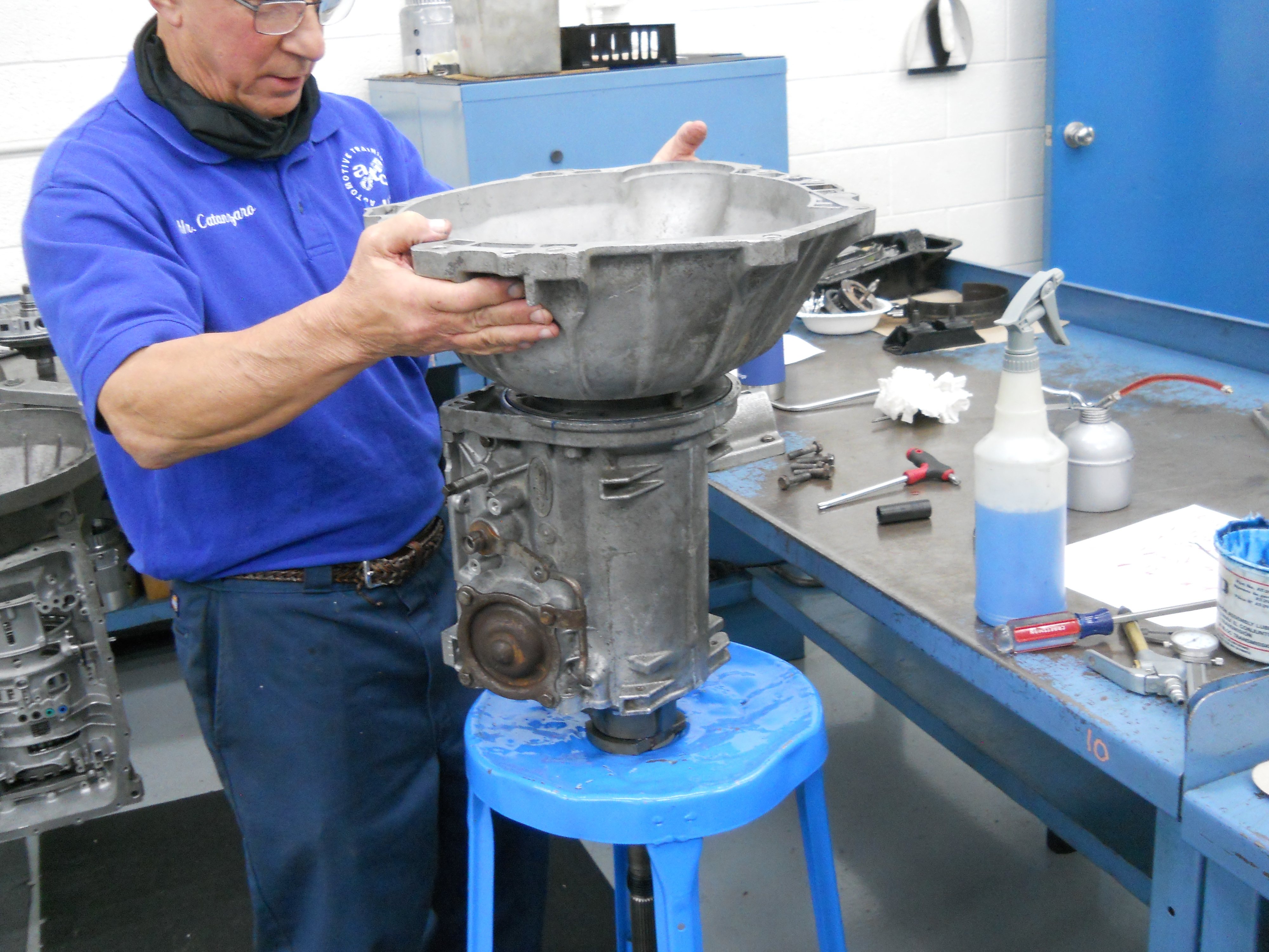
Sun shell, front planet gears, and front ring gear. Valve Body and Front Pump are at the left rear.
[C4-DSCN2796] |
|
|
|
|
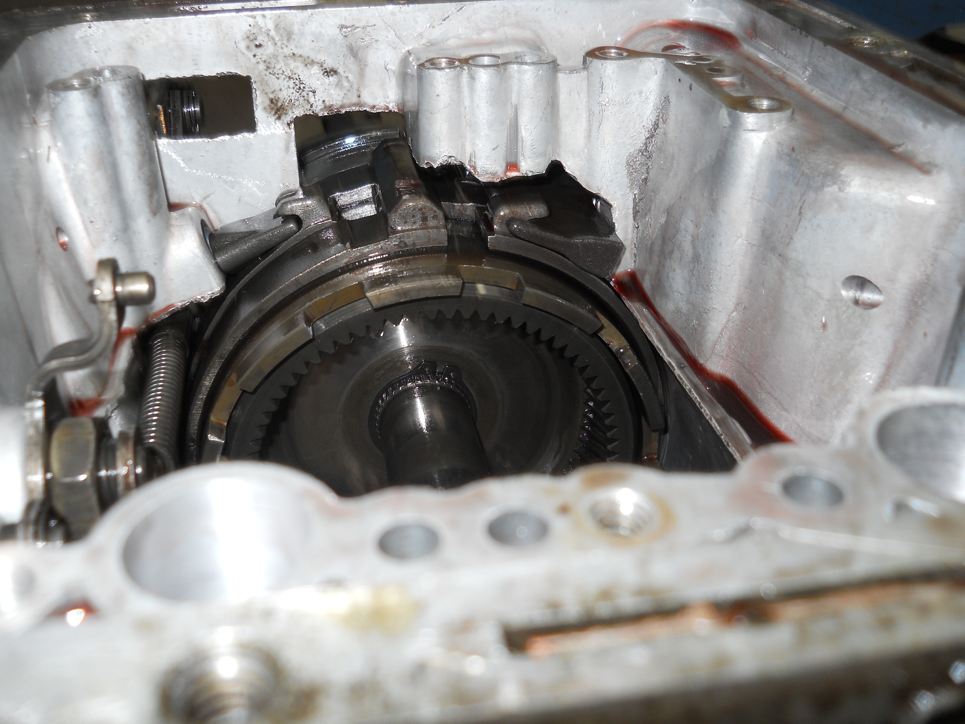
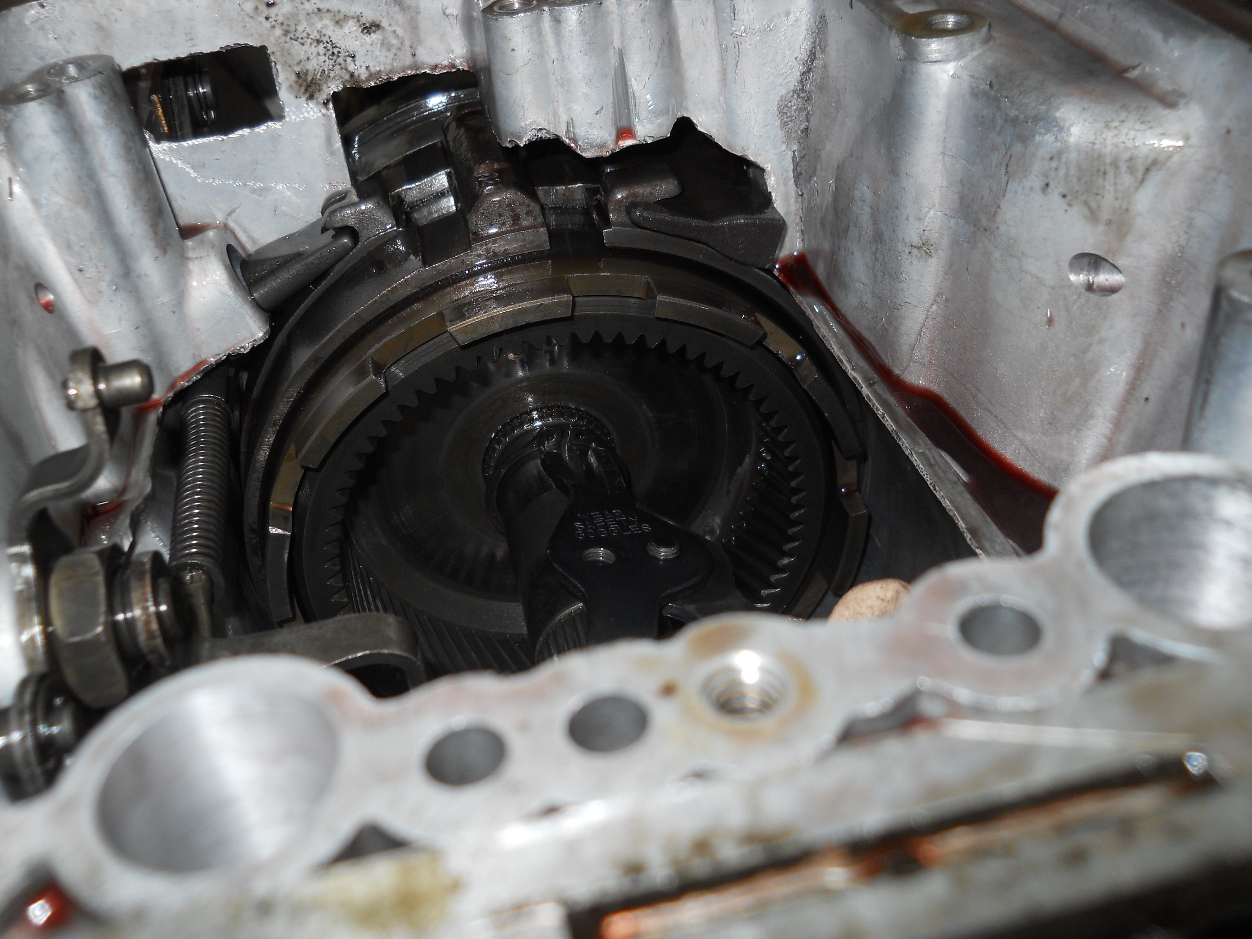
Rear planet gears before removal.
[C4-DSCN2797] |
Rear planet removed from case.
[C4-DSCN2798] |
|
|
|
|
Rear ring gear retaining snap ring which holds the output shaft in place. This snap ring must be removed in order to remove the output shaft, rear ring gear, low/reverse band, and drum from the case.
[C4-DSCN2799] |
Removing the output shaft retaining snap ring.
[C4-DSCN2800] |
|
|
|
|
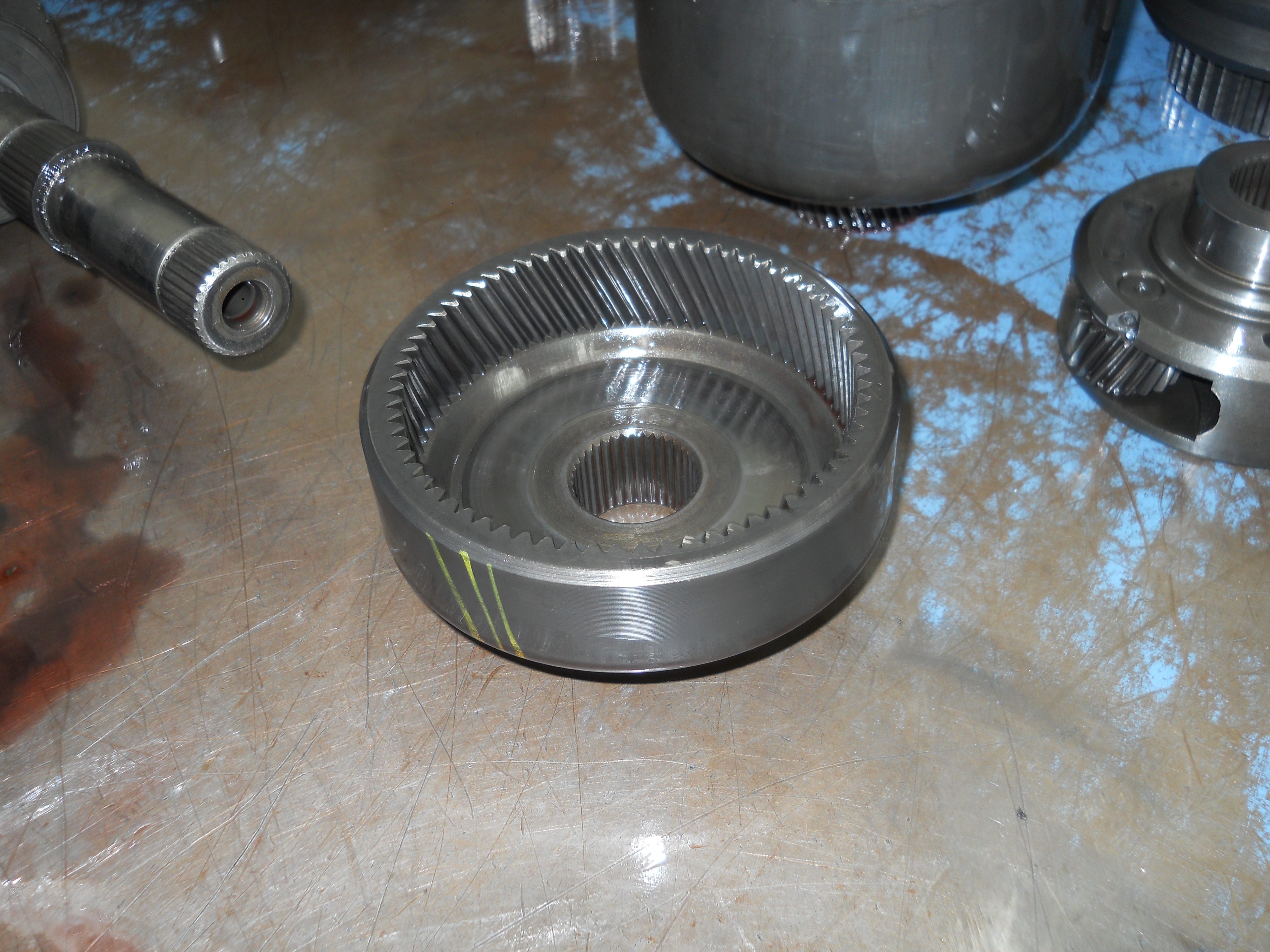
Rear ring gear.
[C4-DSCN2801] |
Low/reverse band and drum can now be removed from case.
[C4-DSCN2802] |
|
|

|
|
Output shaft.
[C4-DSCN2803] |
Removing the Govenor Distributor Sleeve. Four bolts hold it in place.
[C4-DSCN2804] |
|
|
|
|
Parking Gear and Parking Pawl. The pawl engages the gear when the transmission is shifted to "P".
[C4-DSCN2805] |
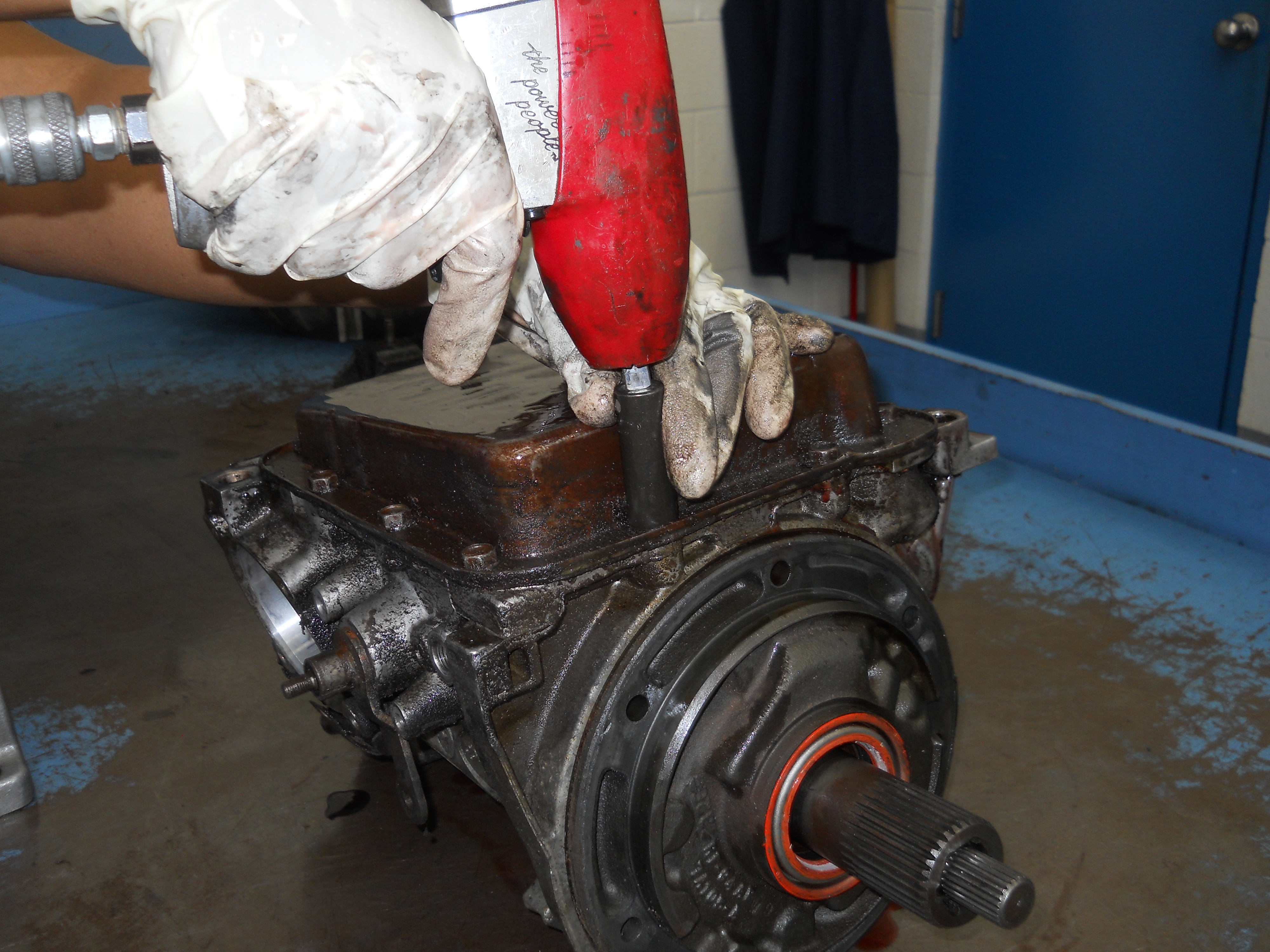
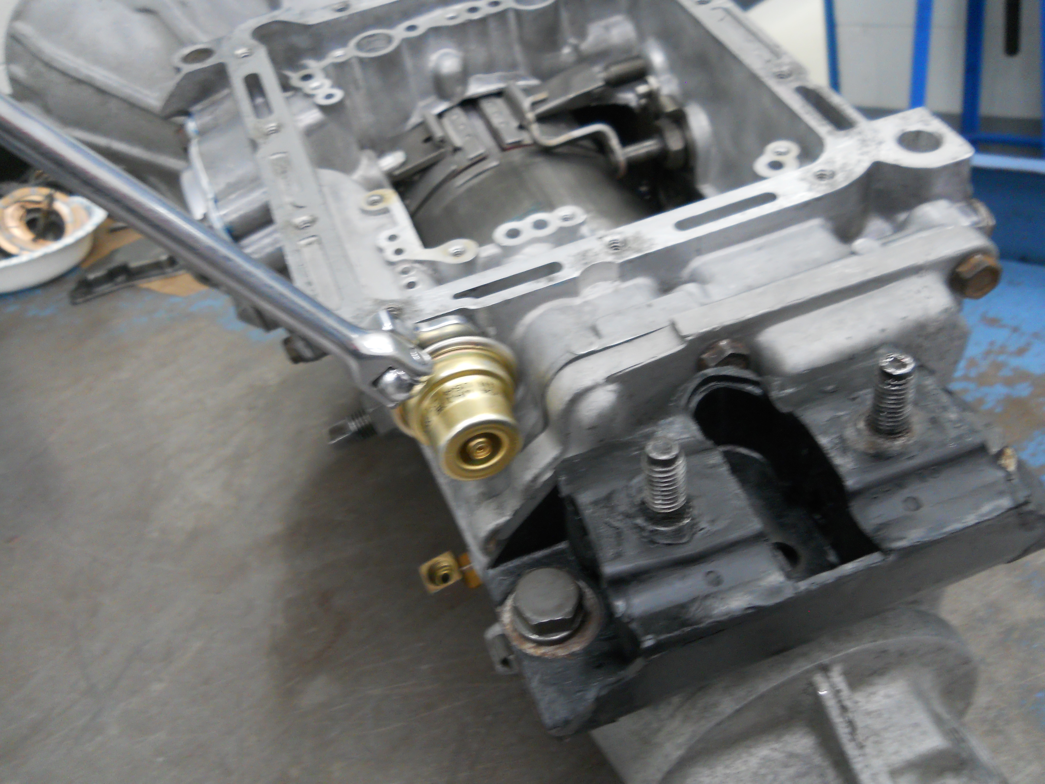
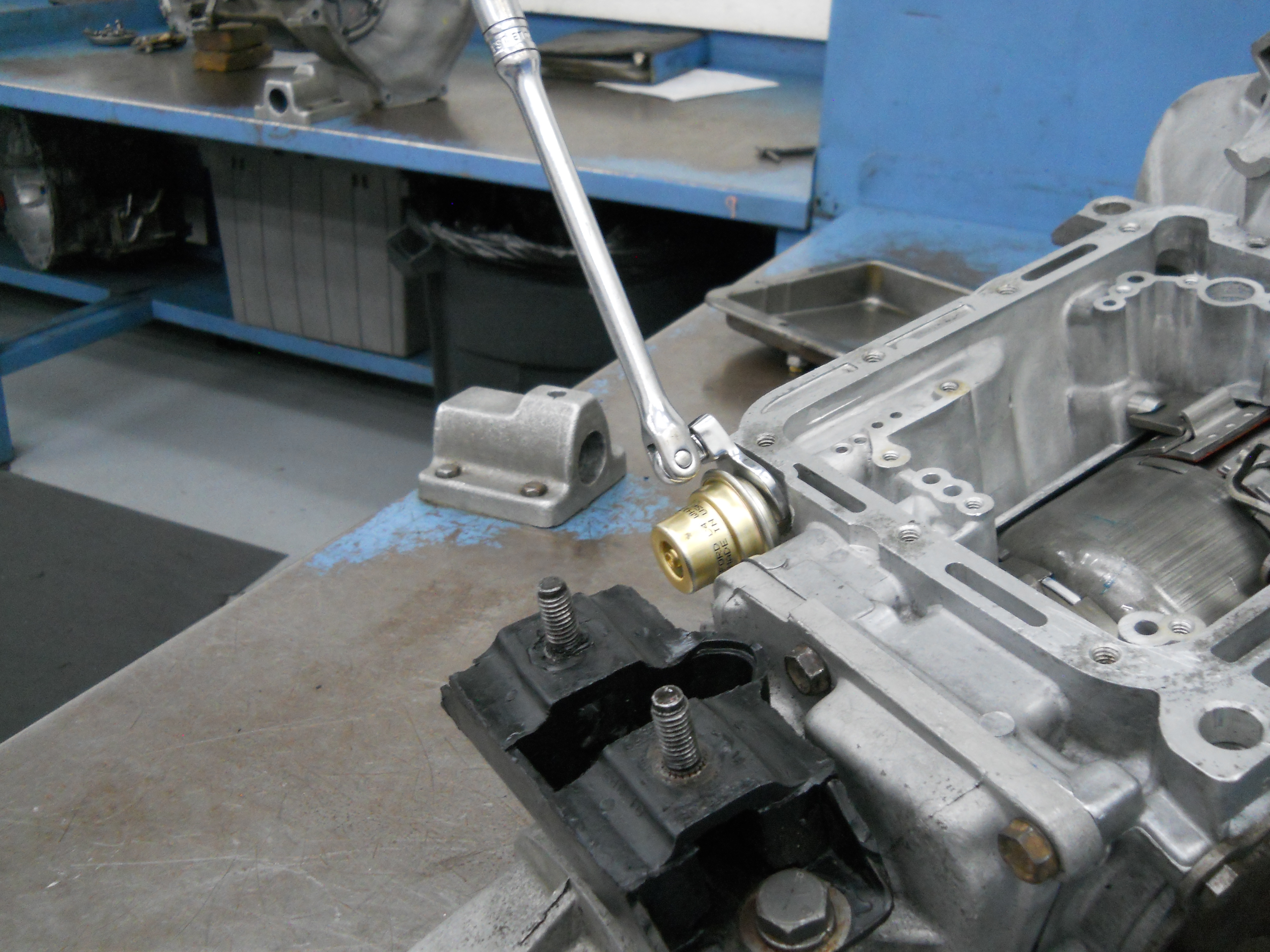
Vacuum Modulator threads into the back of the transmission case. A thin wrench is needed to remove the modulator.
[C4-DSCN2806] |
|
|
|
|
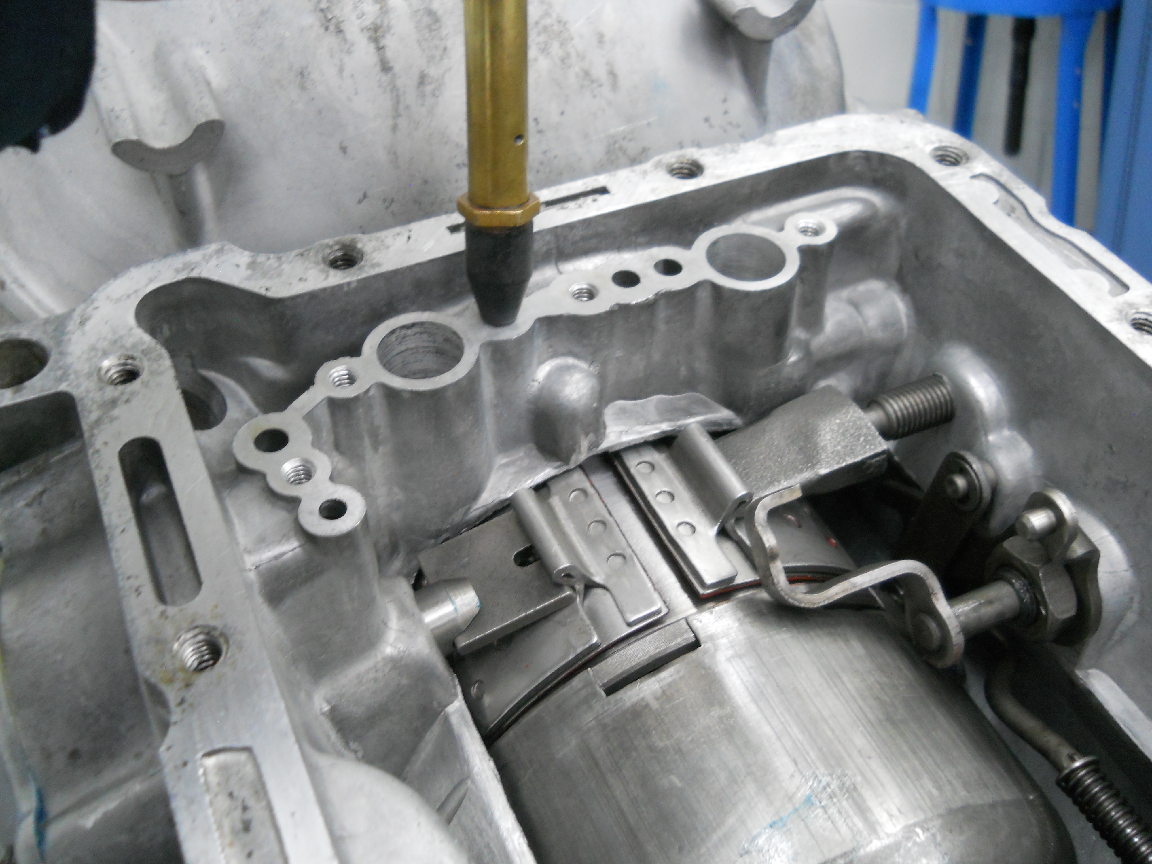
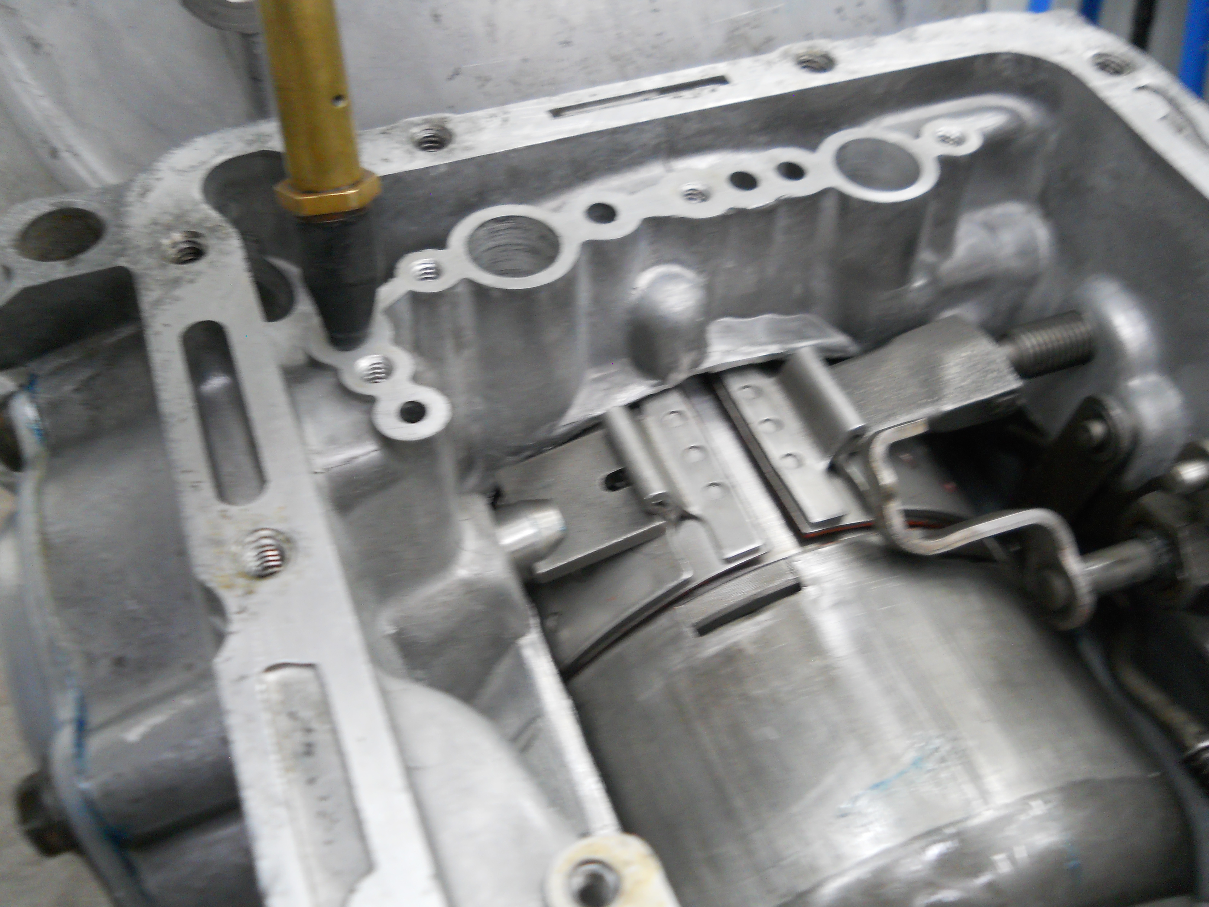
With the Vacuum Modulator removed from the case, the Primary Throttle Valve is exposed and can be removed.
[C4-DSCN2807] |
Front Pump disassembly.
[C4-DSCN2808] |
|
|
CLEANING
|
|
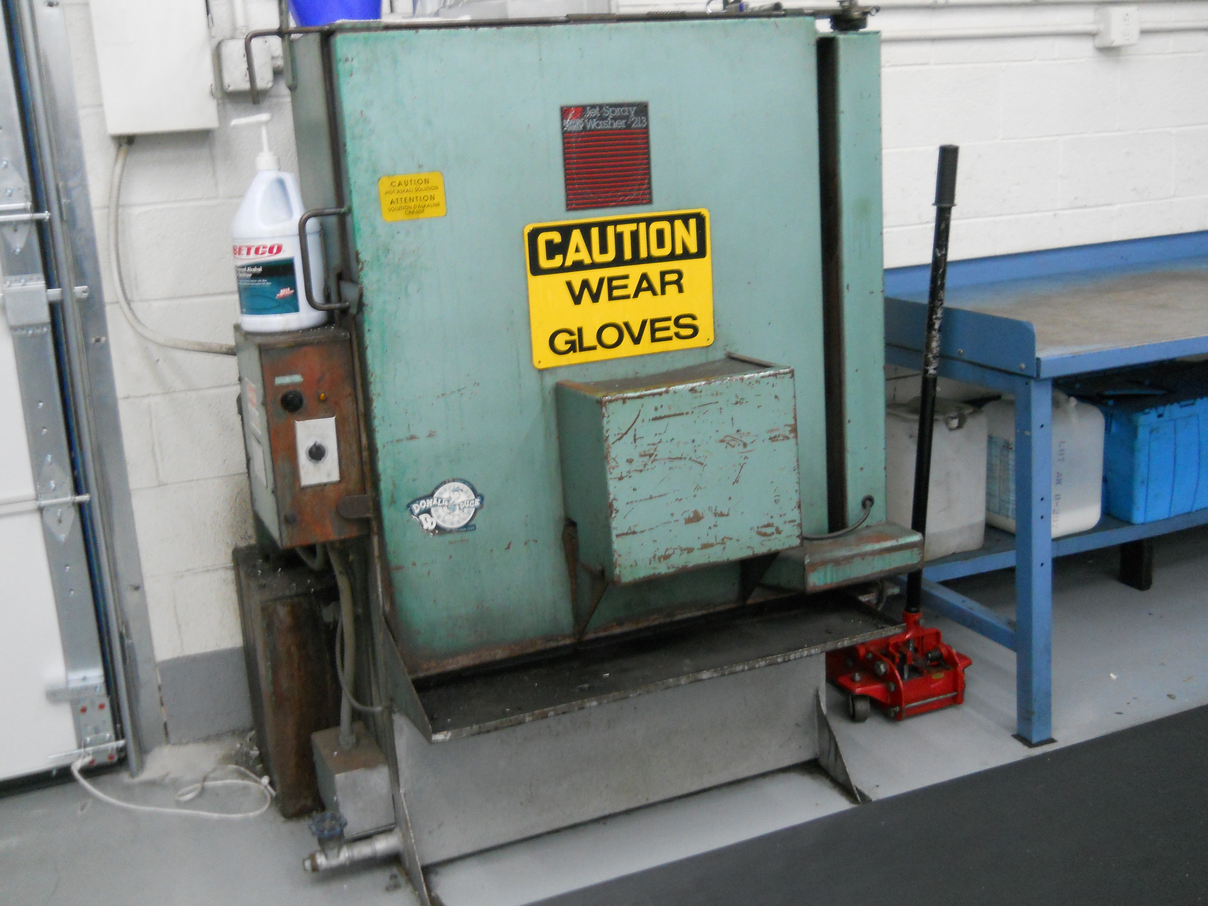
Spray wash cabinet. Transmission is loaded onto the machine and door closed.
[C4-DSCN2858 / C4-DSCN2859] |
|
|
|
|
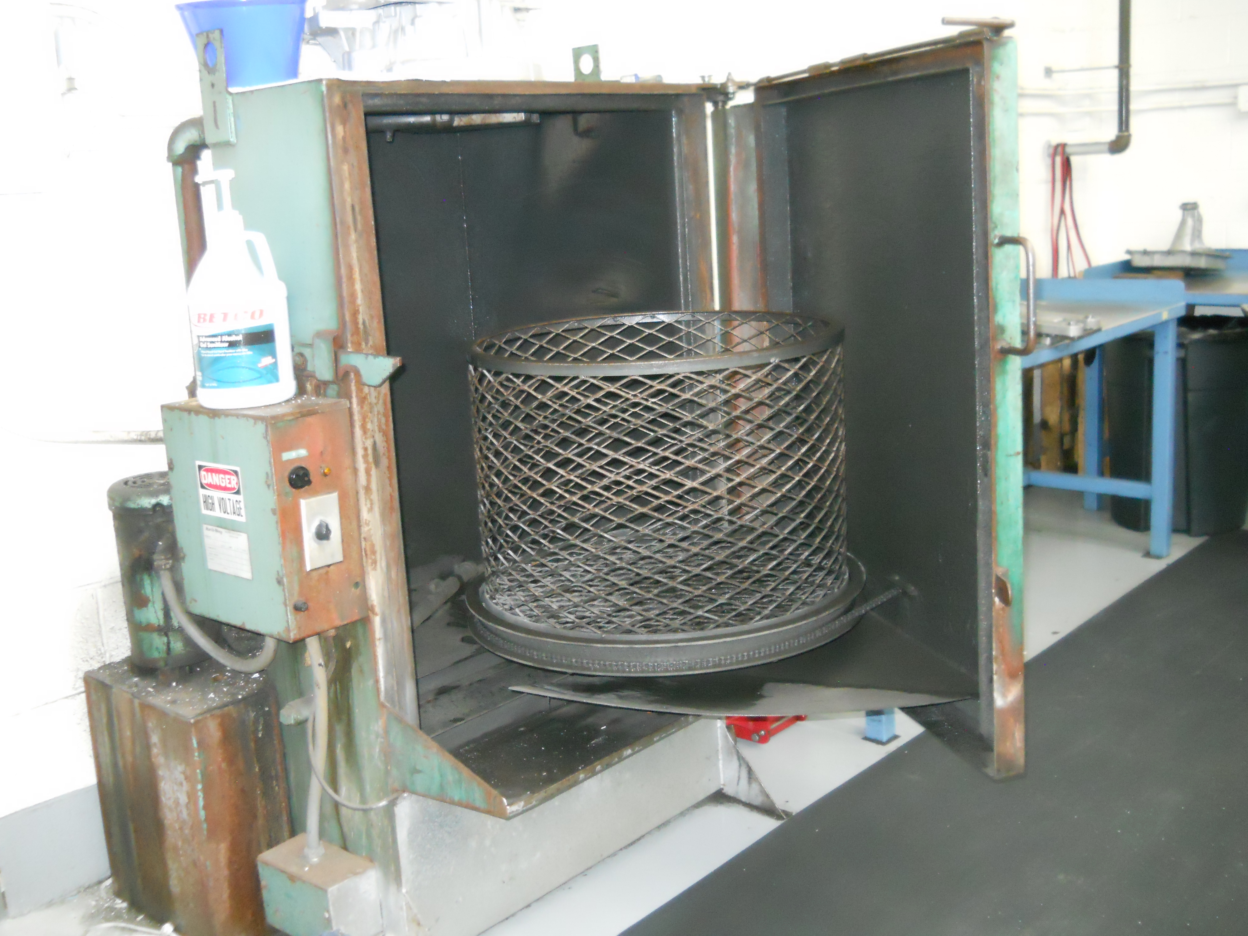
Spray wash cabinet turntable. When turned on, the turntable rotates slowly and 180psi of soap solution at 170°F cleans transmission parts in 20 minutes. Blow dry the parts with compressed air and they are ready for rebuild.
[C4-DSCN2862] |
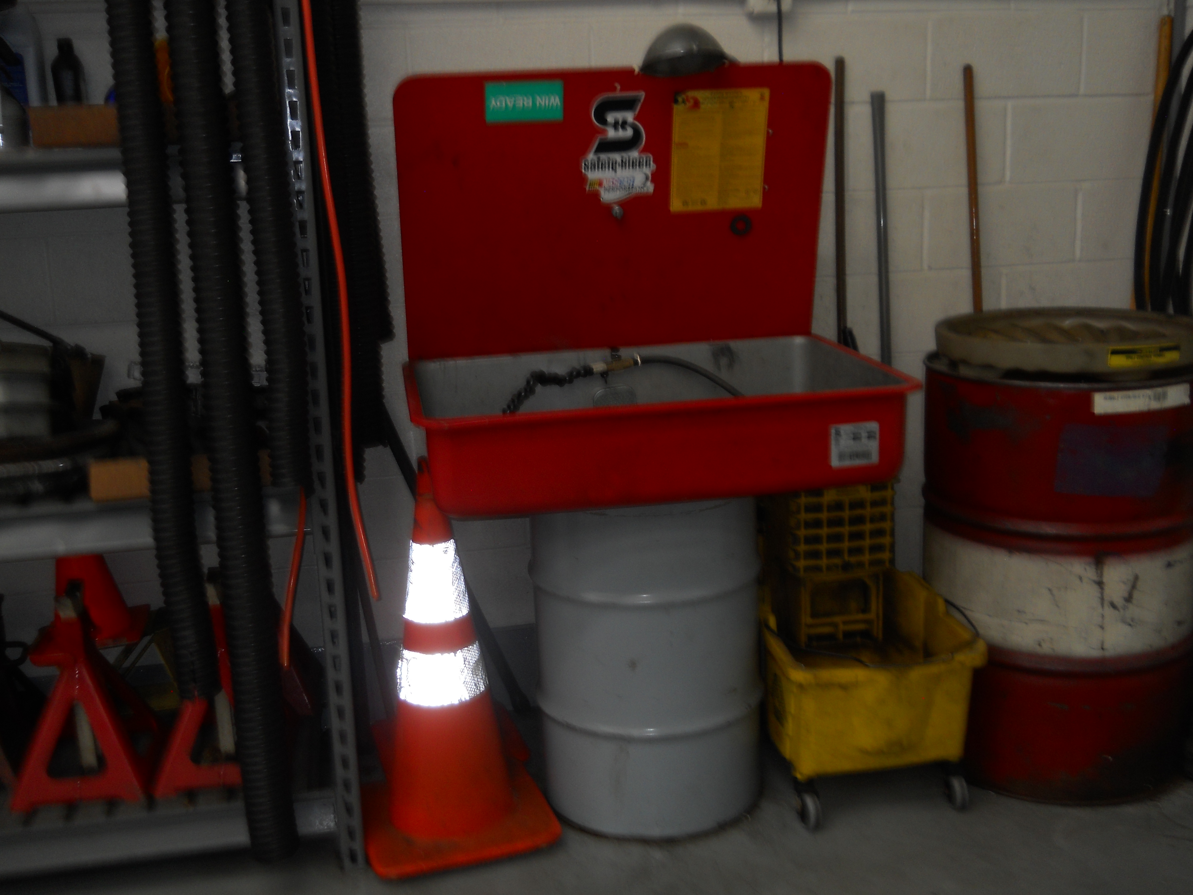
Parts washer. It seems like every shop has one.
[C4-DSCN2863] |
|
|
REASSEMBLY - November 4, 2021
|
|
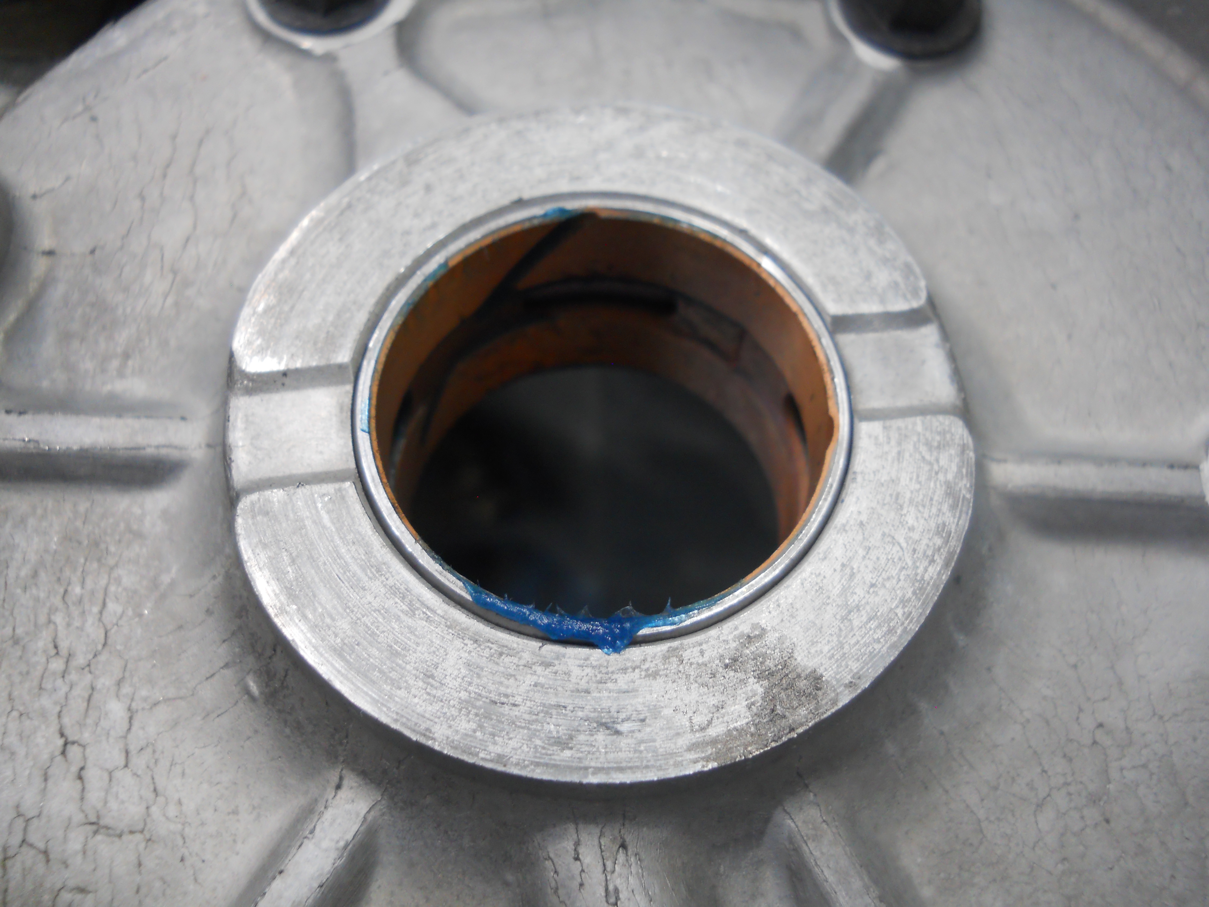
Direct drum new bushing installed.
[C4-DSCN2821] |
New pump bushing installed in front pump and lubricated with TransGel assembly lube.
[C4-DSCN2822] |
|
|

|
|
Sun shell with new bushings installed.
[C4-DSCN2823] |
Front ring gear with new bushing installed
[C4-DSCN2824] |
|
|
|
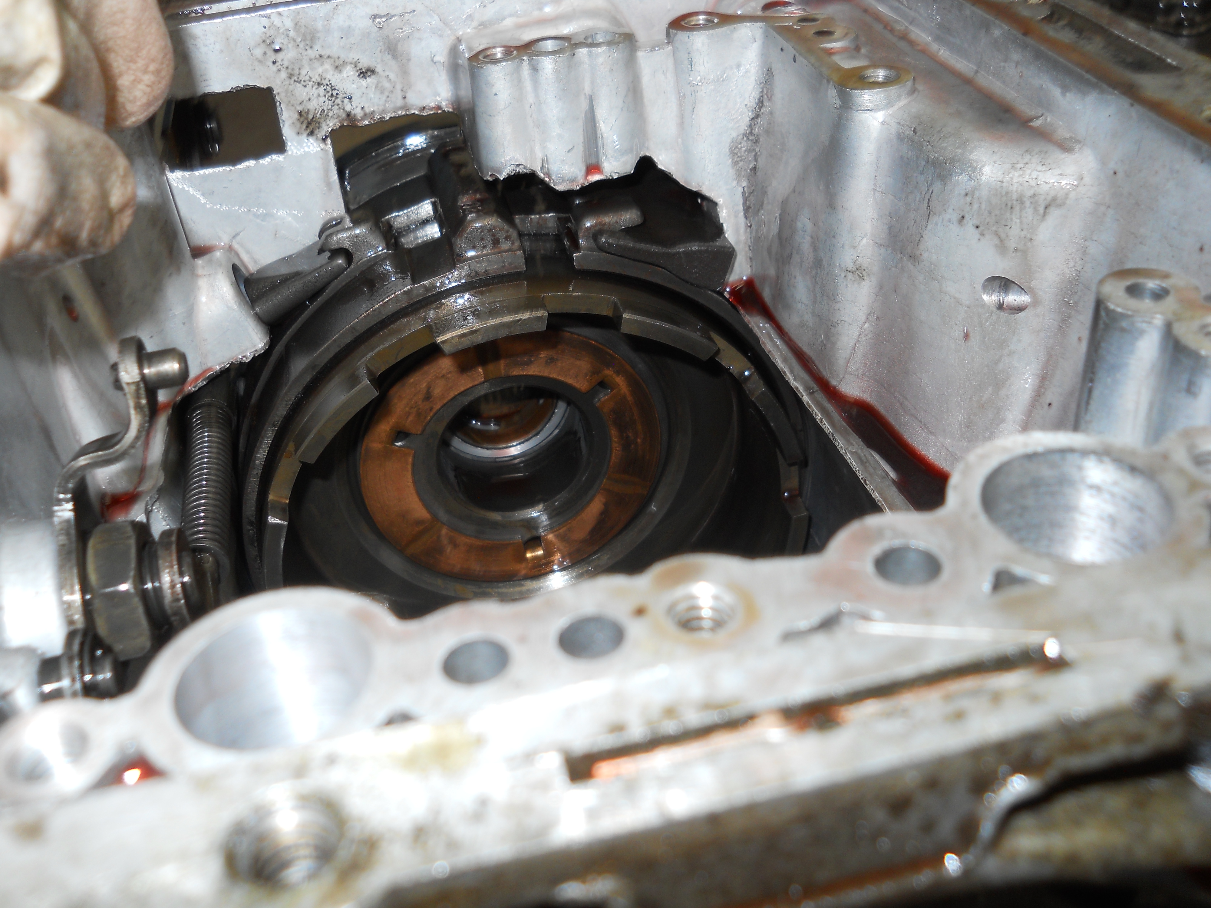
|
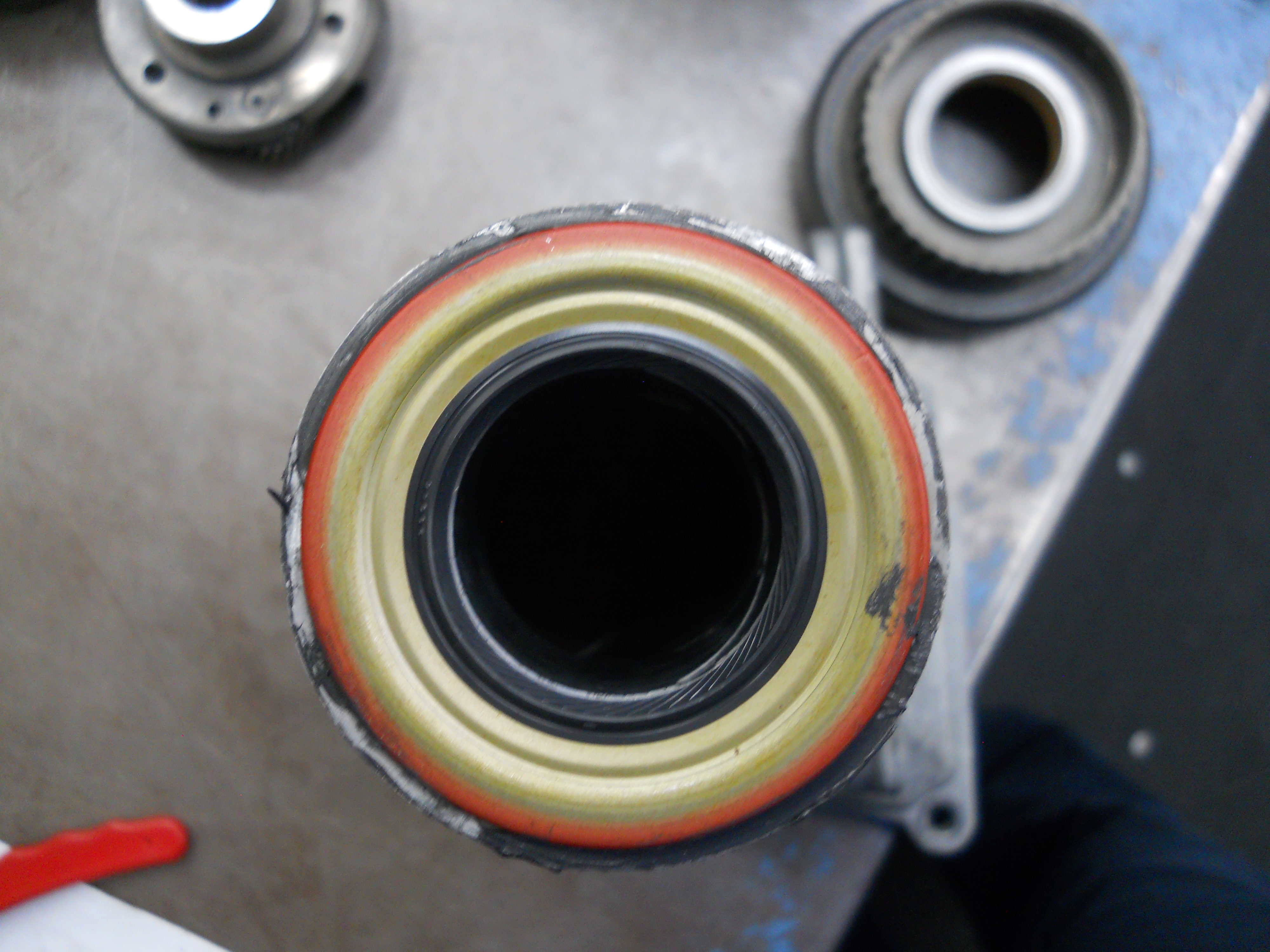
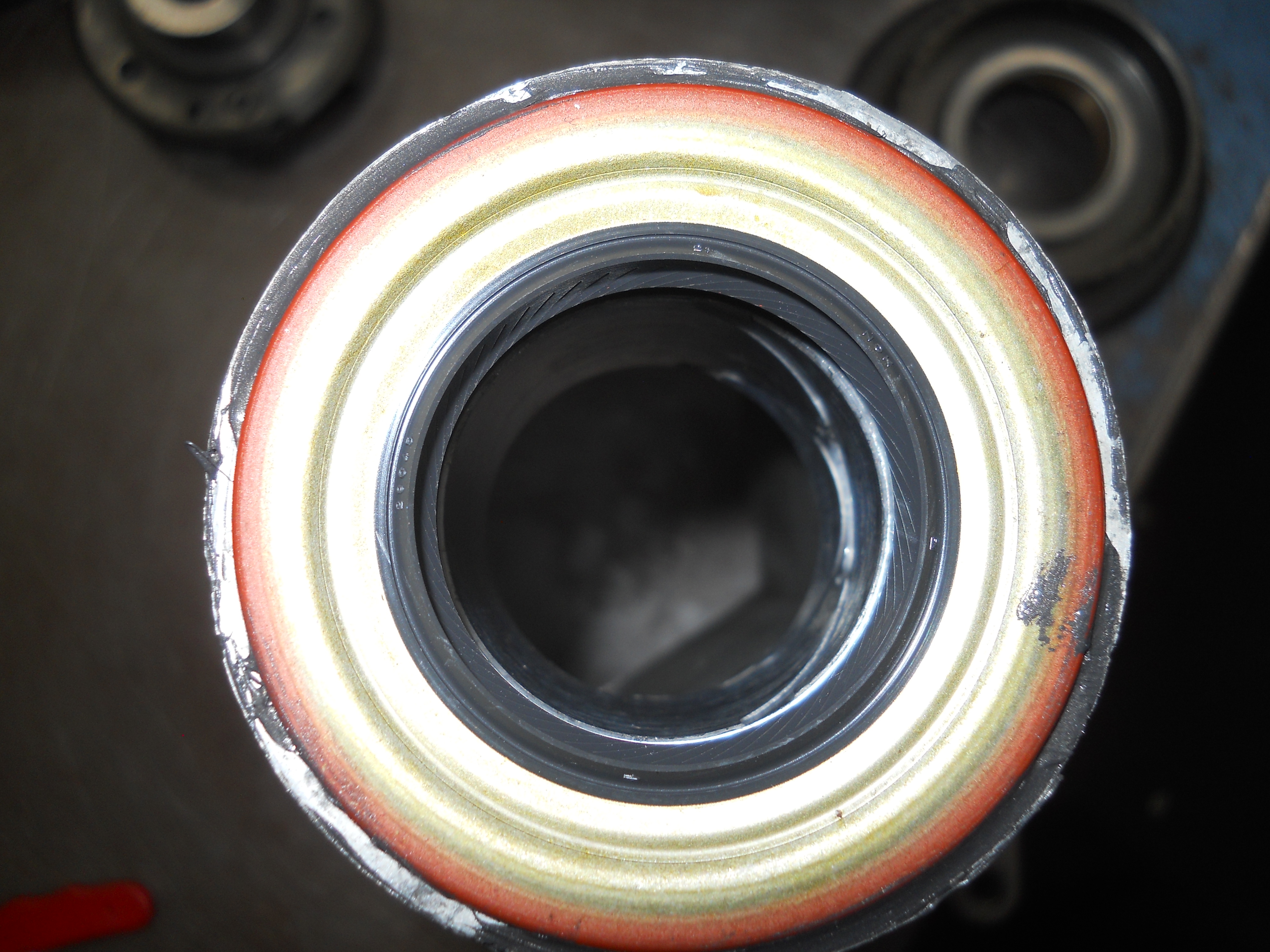
New extension housing bushing and seal are installed. A light coating of RTV is put on outside of seal before installing to prevent leaks.
[C4-DSCN2825 / C4-DSCN2826] |
|
|
|
|
[C4-DSCN2829] |
[C4-DSCN2830] |
|
|
|
|
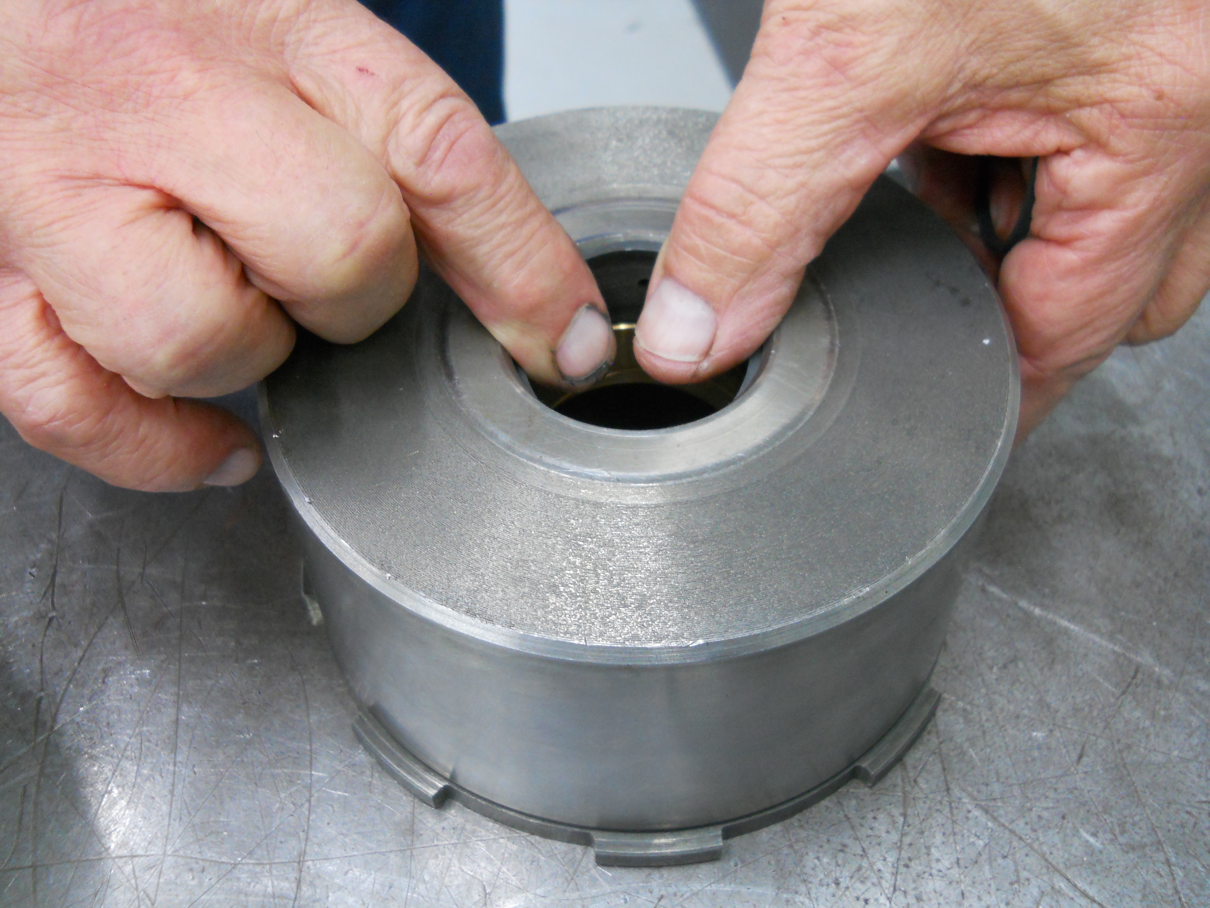
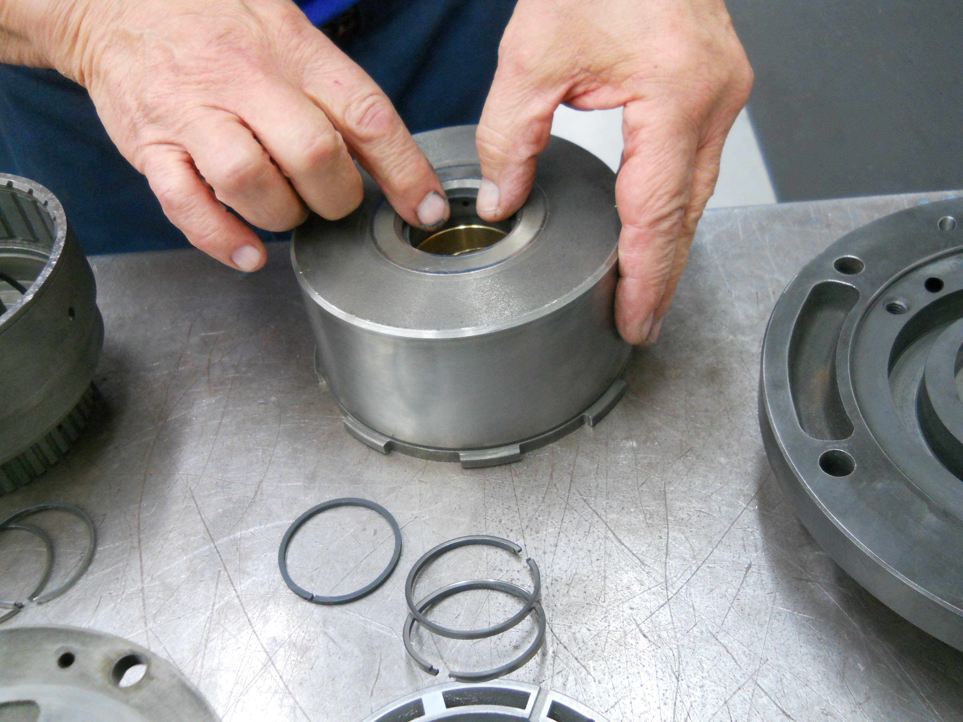
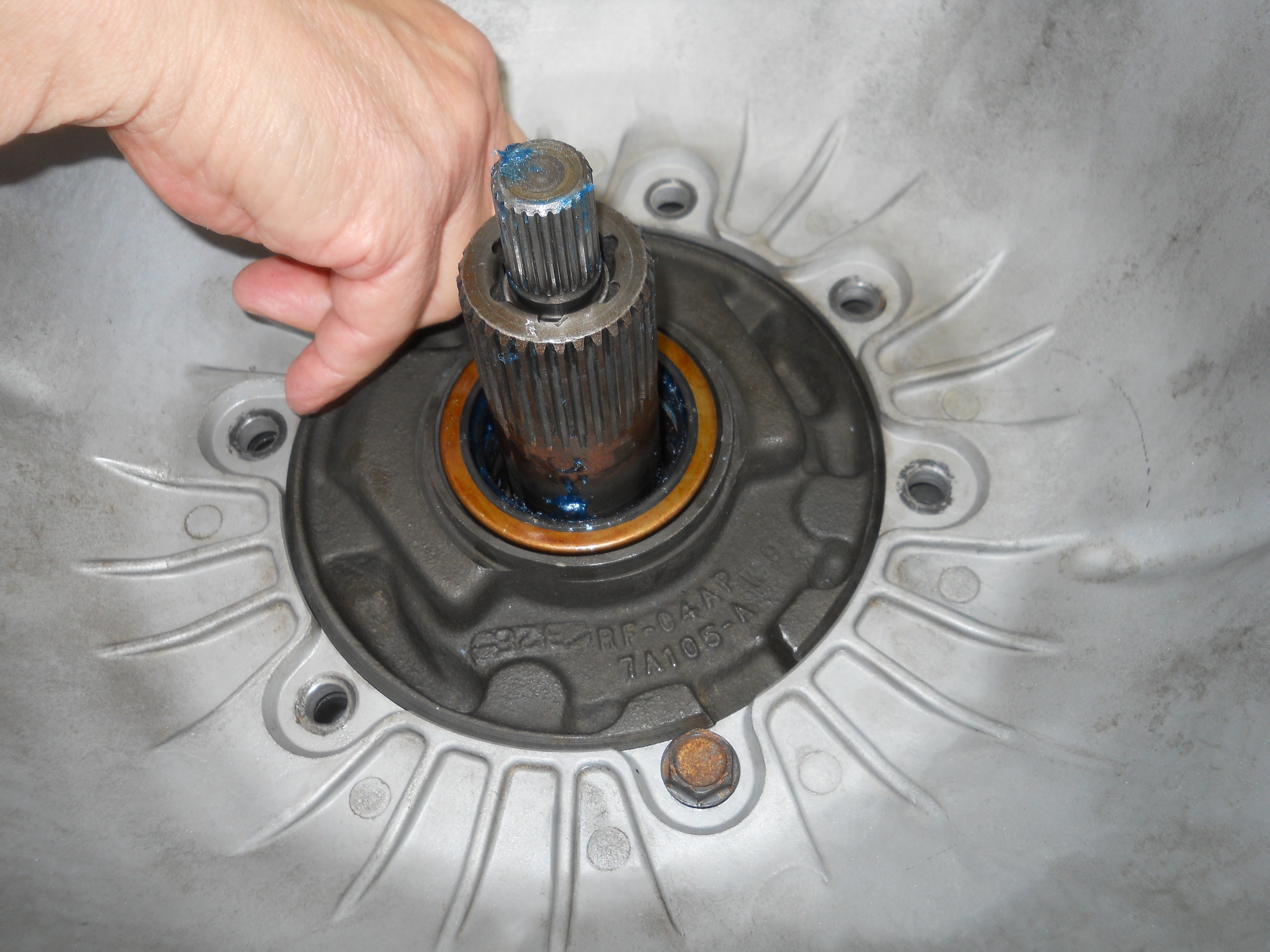
Checking pump stator metal sealing ring fit to verify correct rings are installed in correct location. Forward drum rings are smaller. Mixing rings up causes slippage in forward, direct, and reverse.
[C4-DSCN2831] |
|
|
|
|
|
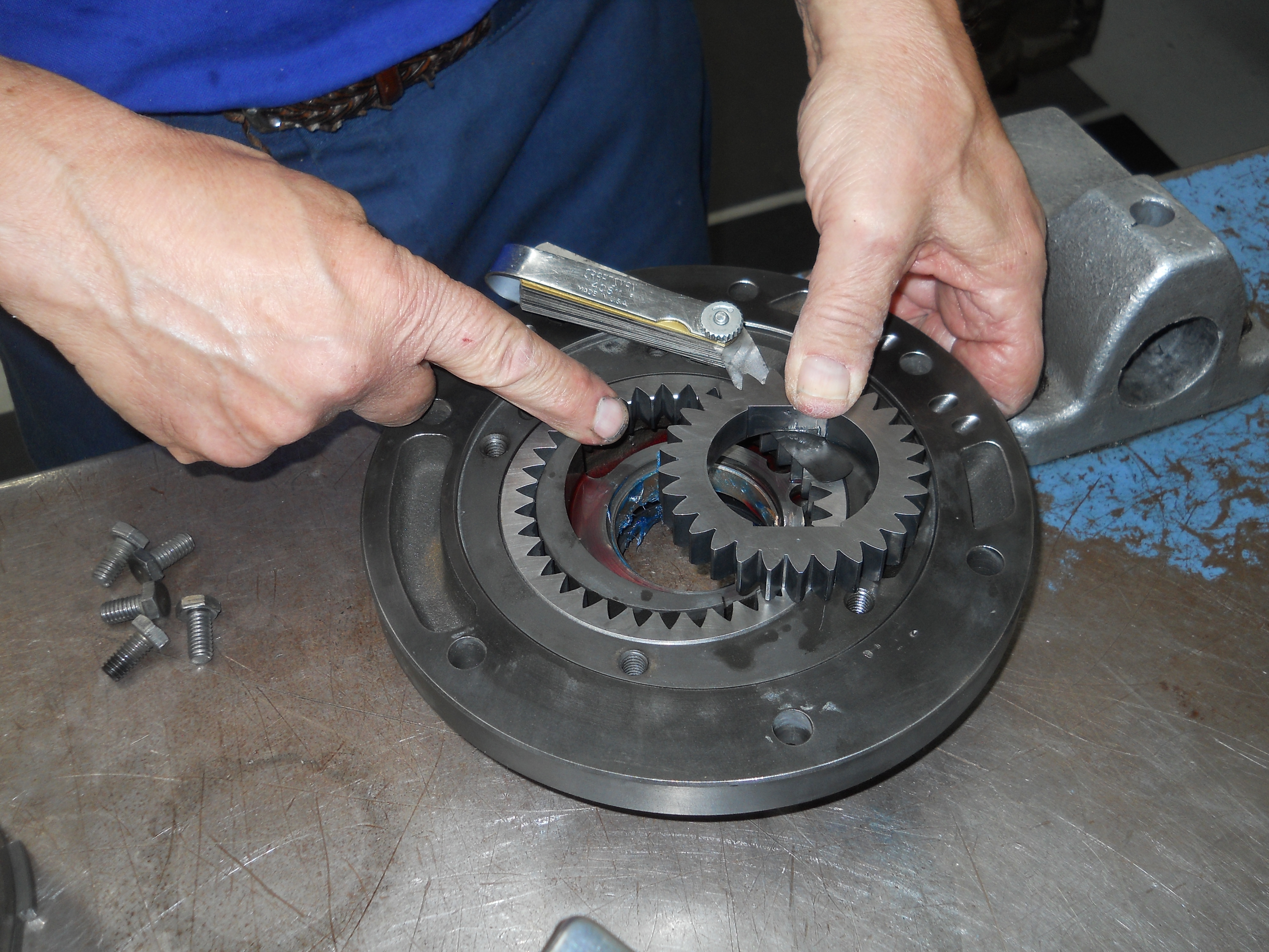
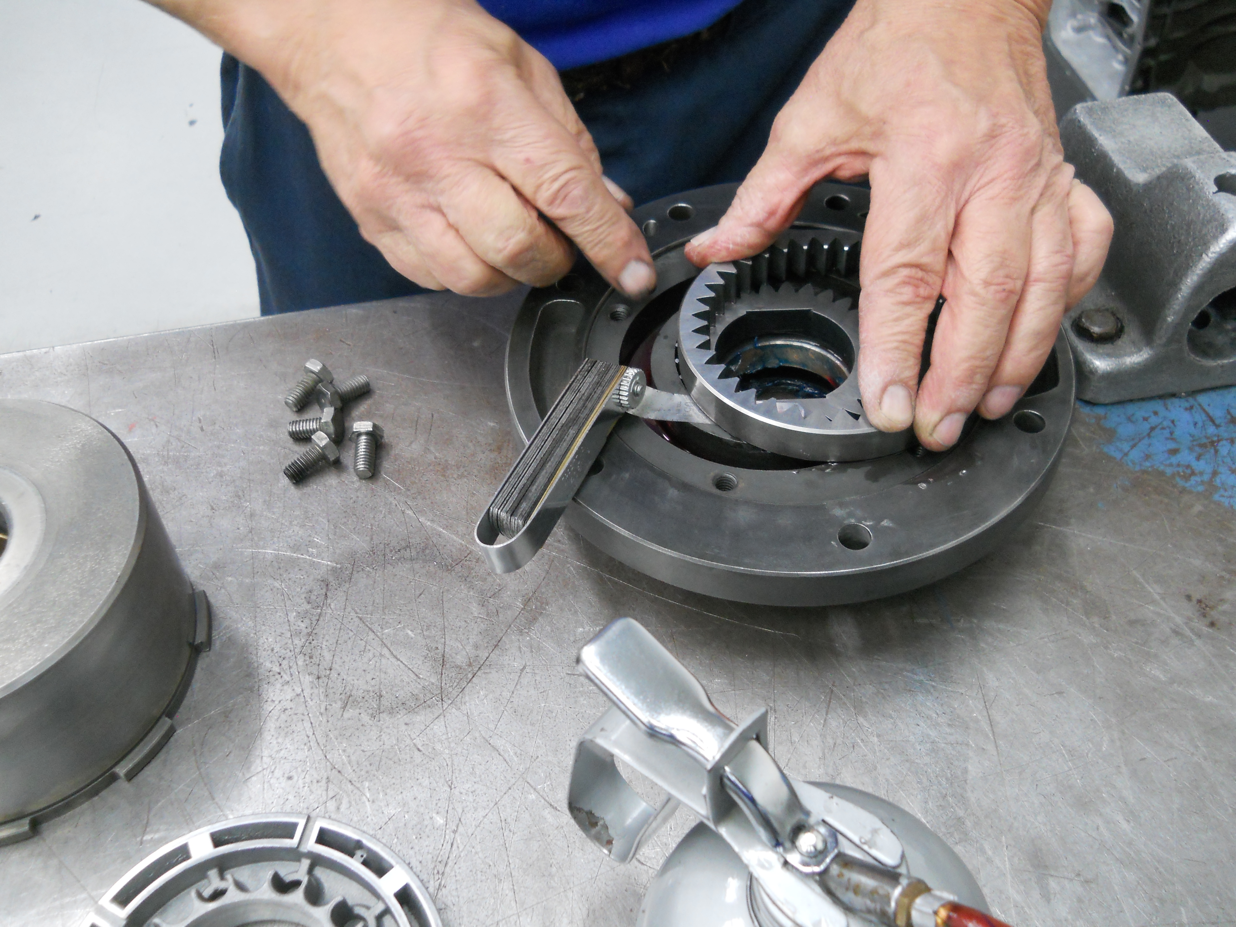
Checking Front Pump clearances.
[C4-DSCN2833 / C4-DSCN2834] |
|
|
|
|
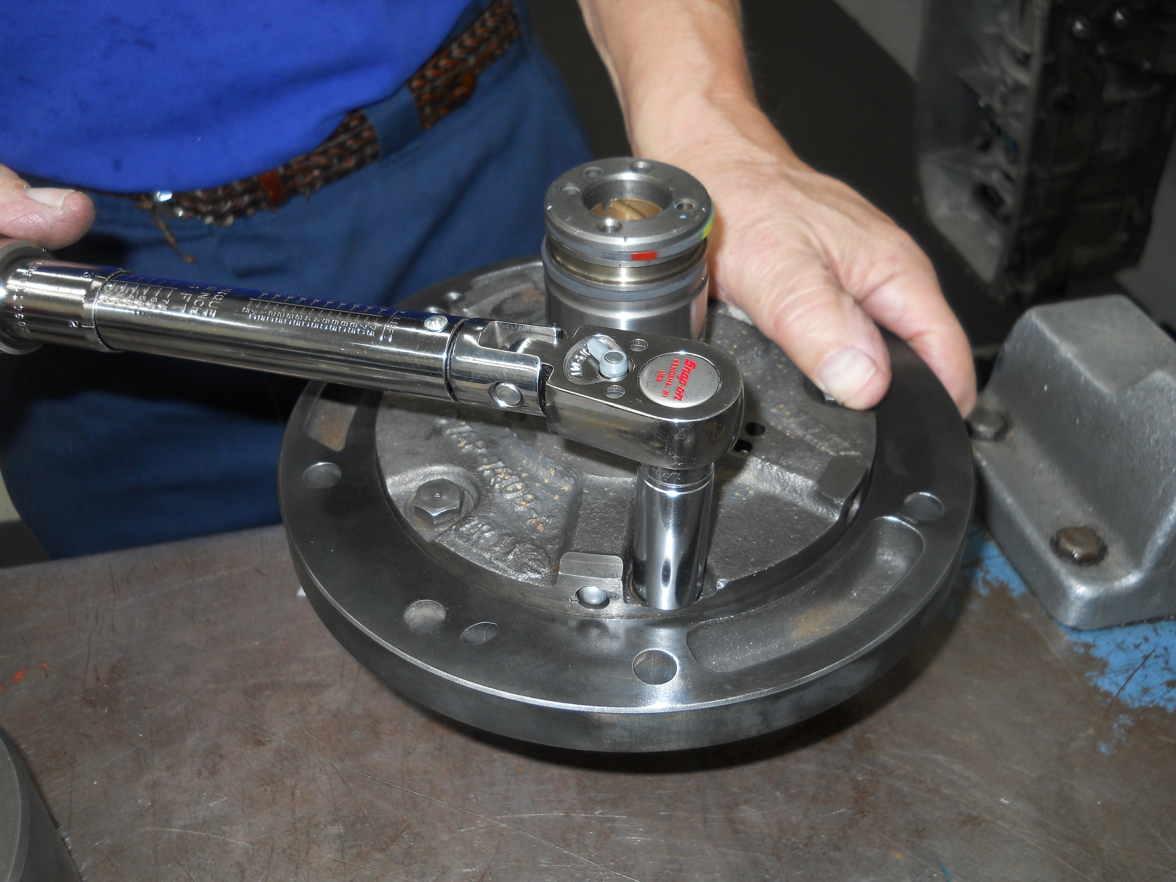
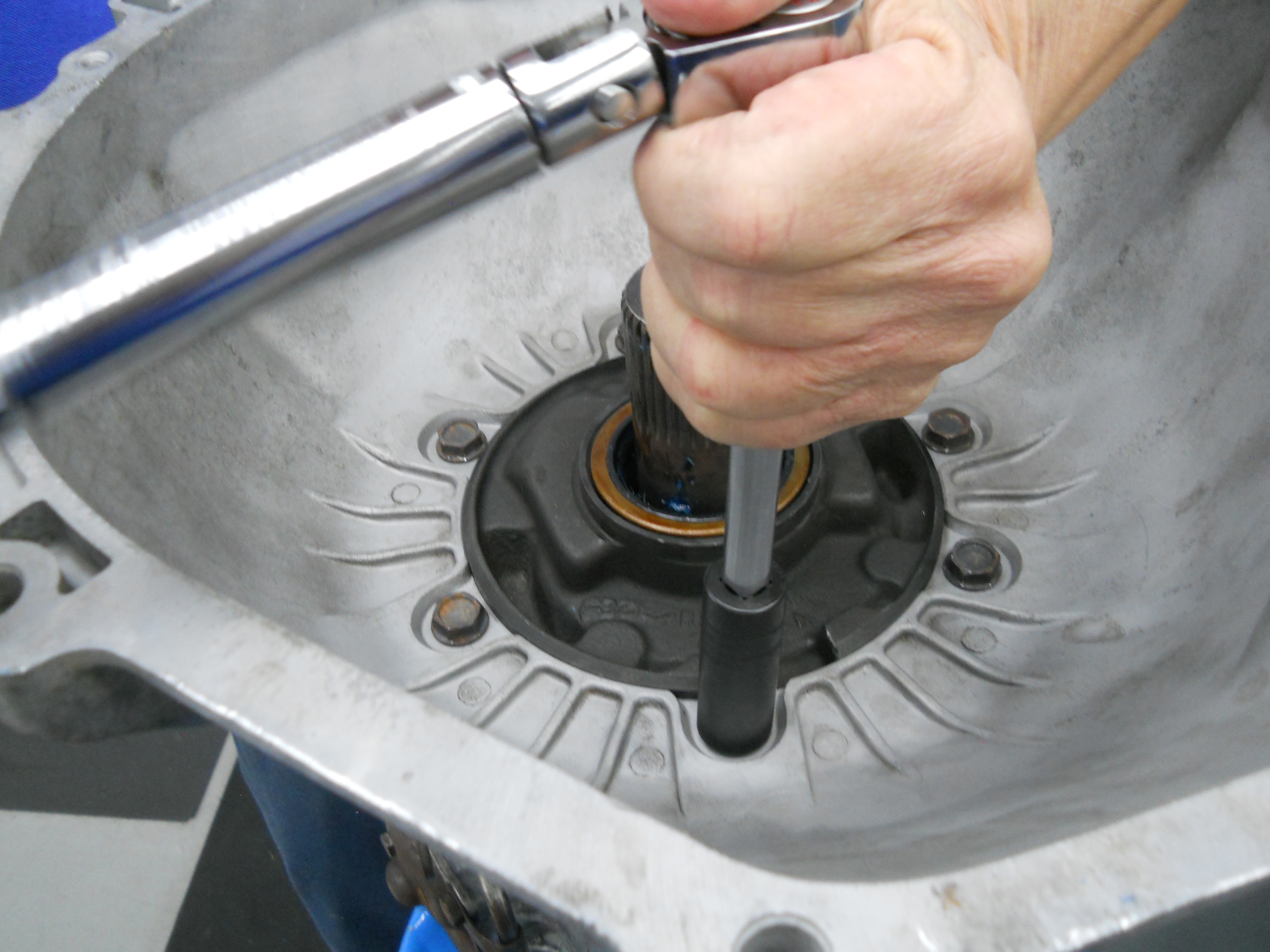
Applying torque to the Front Pump Assembly.
[C4-DSCN2835] |
Applying torque to Low-Reverse Servo Cover. These bolts are torqued to 12-20 ft-lb while the Intermediate Servo Cover Bolts are torqued to 16-22 lb-ft.
[C4-DSCN2836] |
|
|
|
|
Parking Gear and Parking Pawl are loaded into the case. A little assembly grease helps things out.
[C4-DSCN2837] |
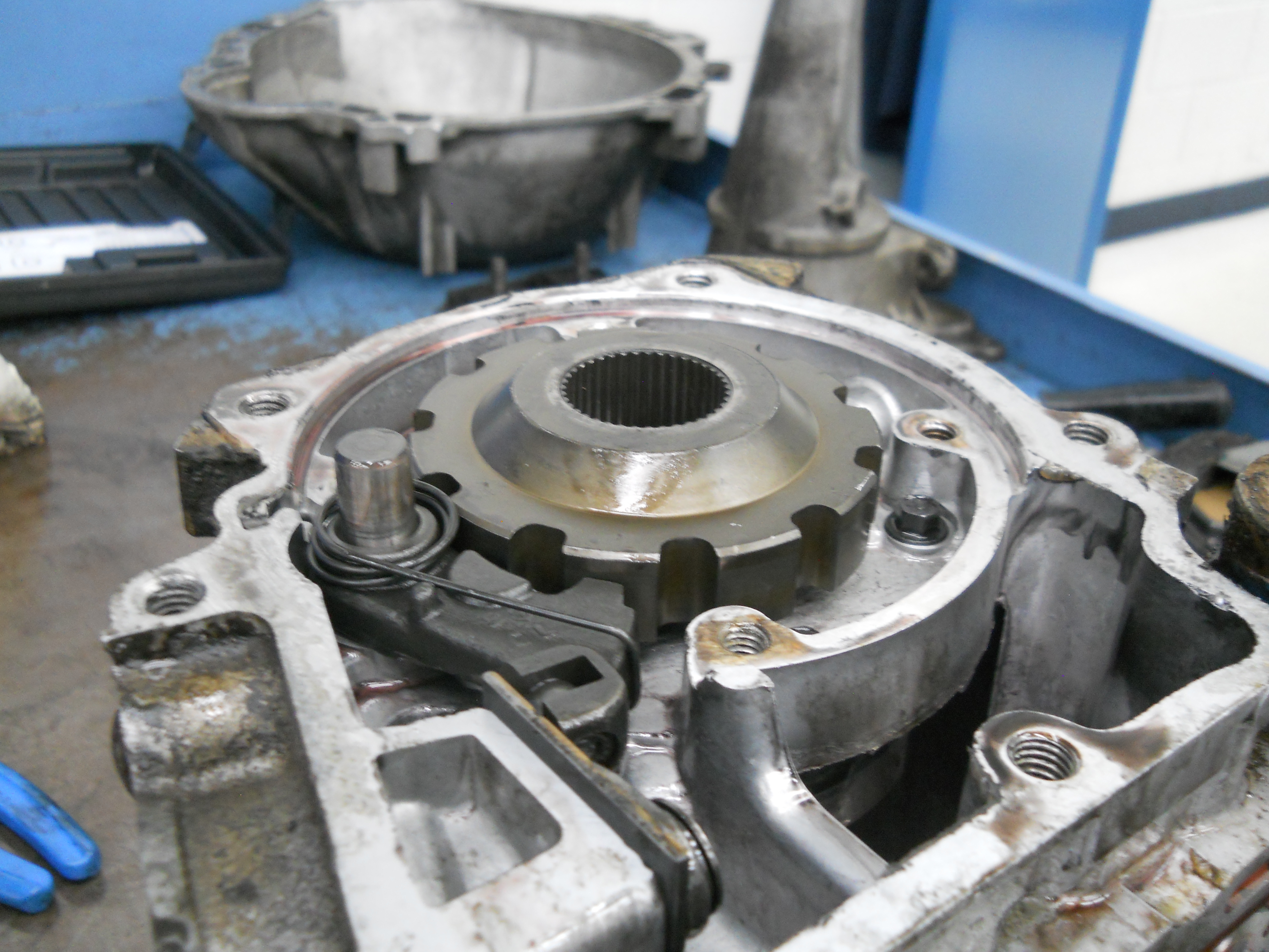
Distributor Sleeve is bolted to the back of the case.
[C4-DSCN2838] |
|
|
|
|
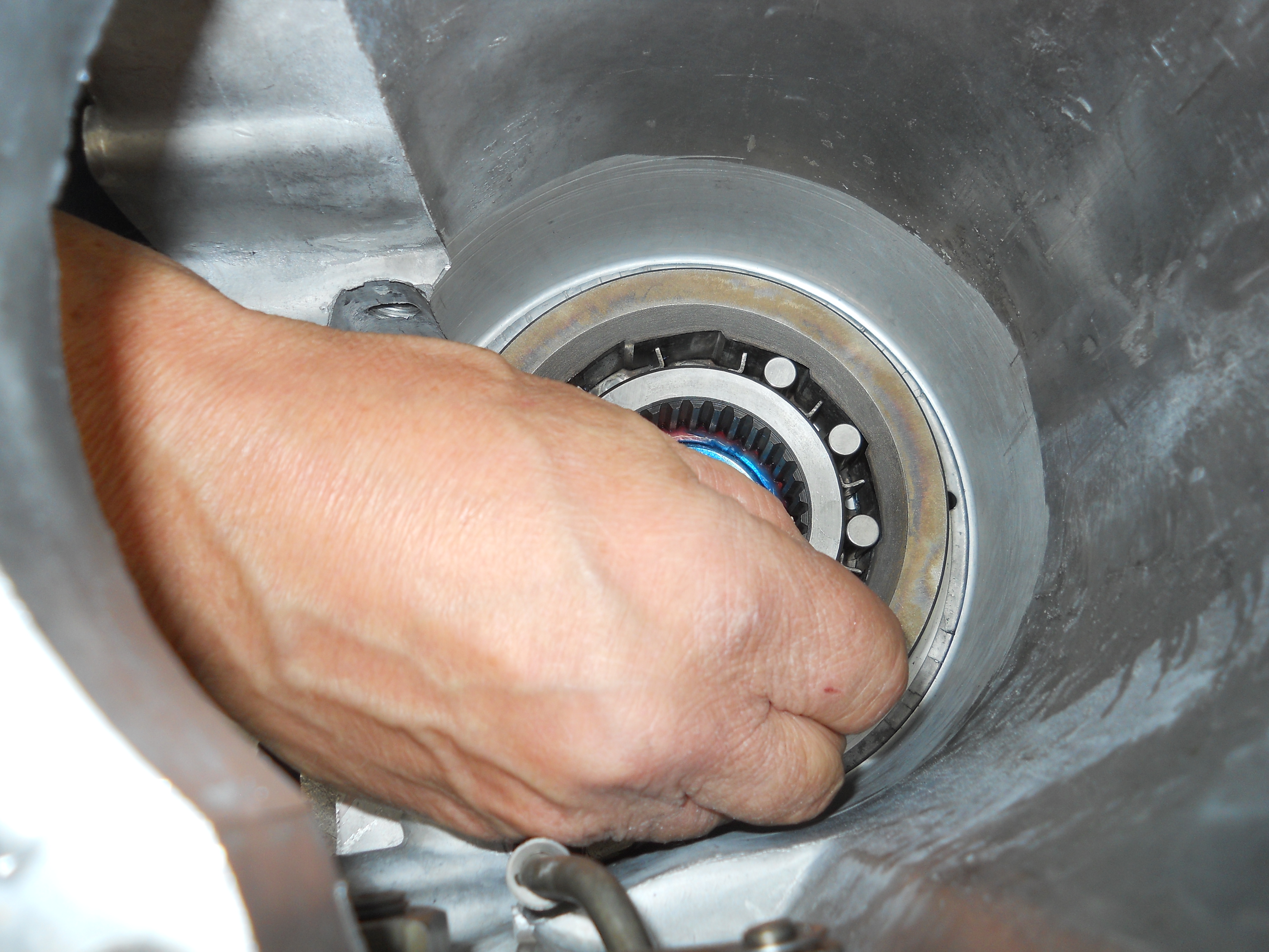
Installing new one way clutch element. One way clutch locks the low/reverse drum to the case in Drive so vehicle can take off in 1st gear. In low gear the low/reverse band locks the low/reverse drum to the case.
[C4-DSCN2839] |
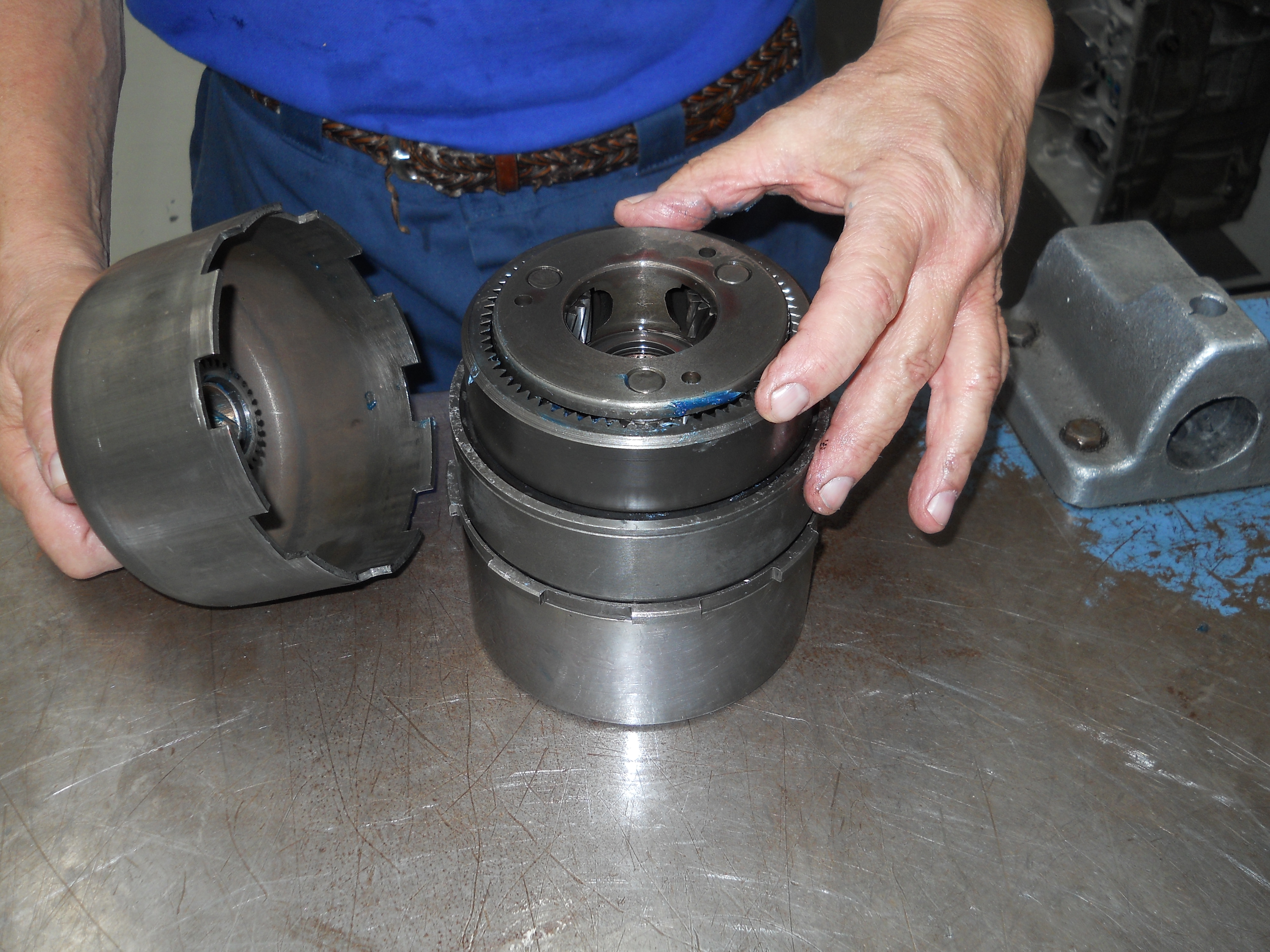
Stacking up the direct drum, forward drum, front ring gear, front planet, and sun shell. These parts must be assembled together so they can be installed into the transmission case.
[C4-DSCN2840] |
|
|
|
|
Lubricating the thrust surface on sun shell.
[C4-DSCN2841] |
Lubricating the sun shell bushings.
[C4-DSCN2842] |
|
|
|
|
Intermediate Band is slid into place.
[C4-DSCN2843] |
Old shop stool makes a great fixture for holding case during assembly operations.
[C4-DSCN2844] |
|
|
|
|
Installing the band struts to the servo and band aduster for 2nd gear.
[C4-DSCN2845] |
Lubricating the pump washer thrust surface with 50-50 mix of ATF and STP. Like an engine the ATF will drain off the part if it sits. This mix prevents that and does a better job of lubrication on initial start up. This mix was put on all bushing journals and thrust washers and their corresponding thrust washer surface
[C4-DSCN2846] |
|
|
|
|
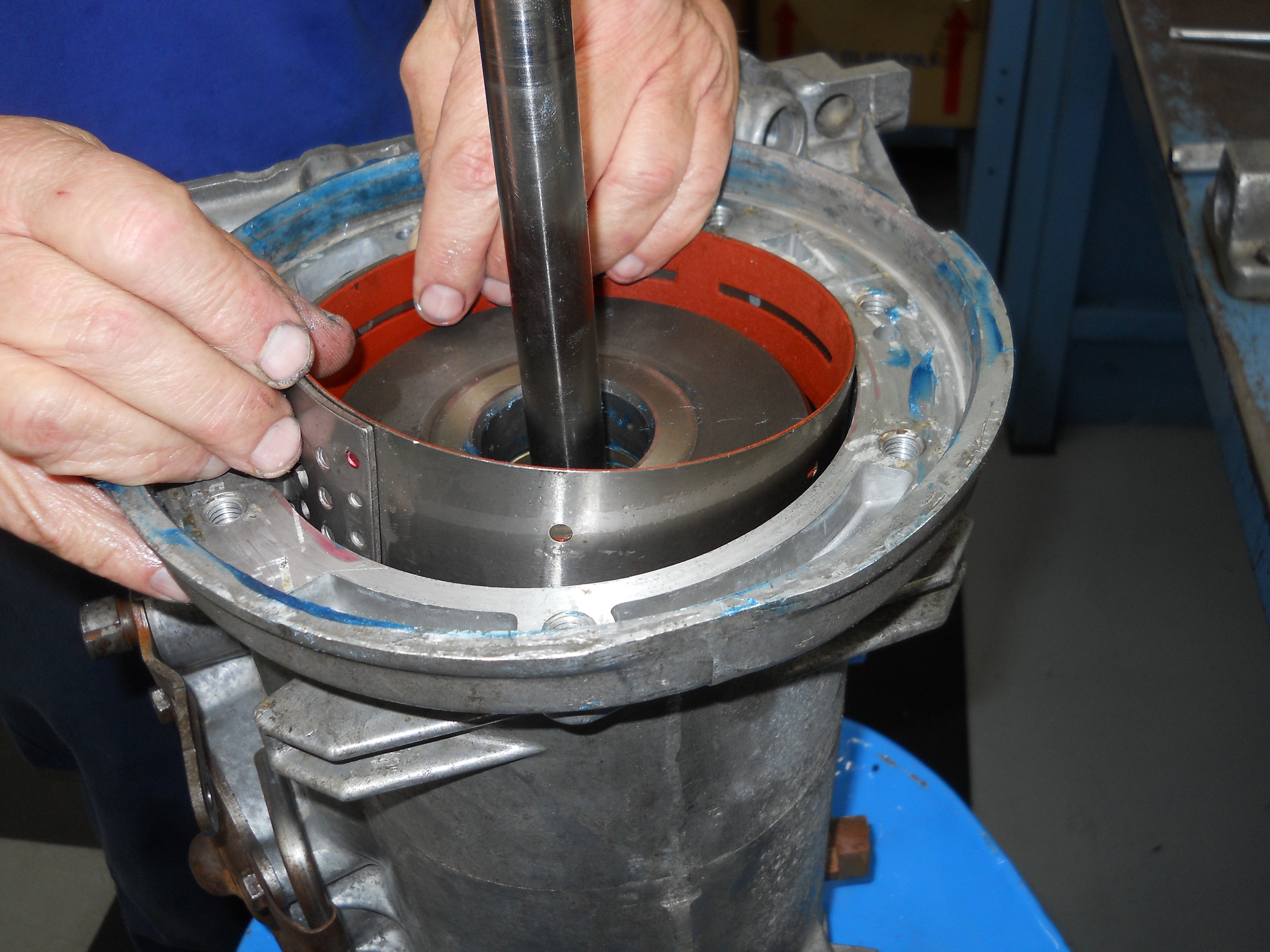
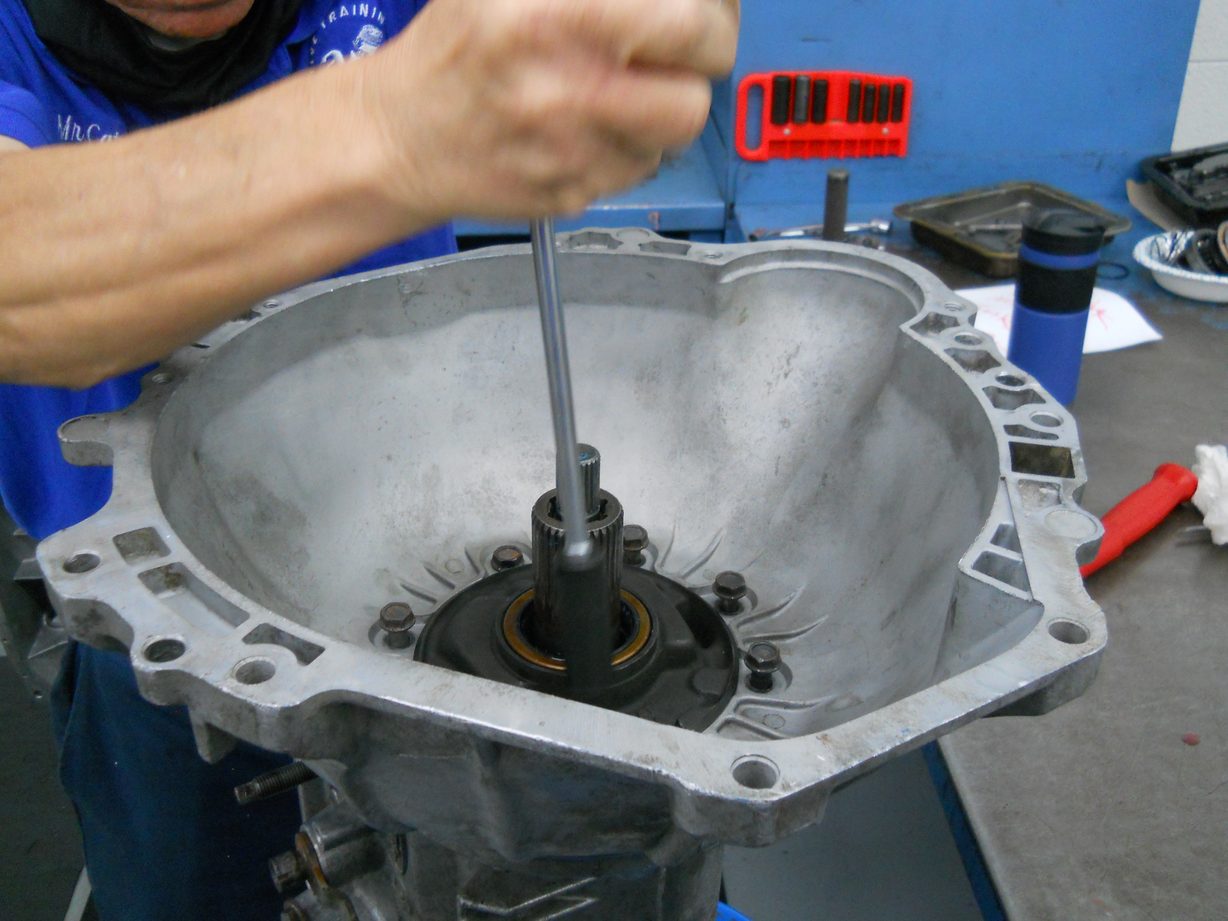
Front Pump and Input Shaft are loaded into the case.
[C4-DSCN2847] |
Front Pump is aligned to case. It only fits one way. Front Pump is held in place by Bell Housing. The smaller shaft shown here is the 24 spline input shaft.
[C4-DSCN2848] |
|
|

|
|
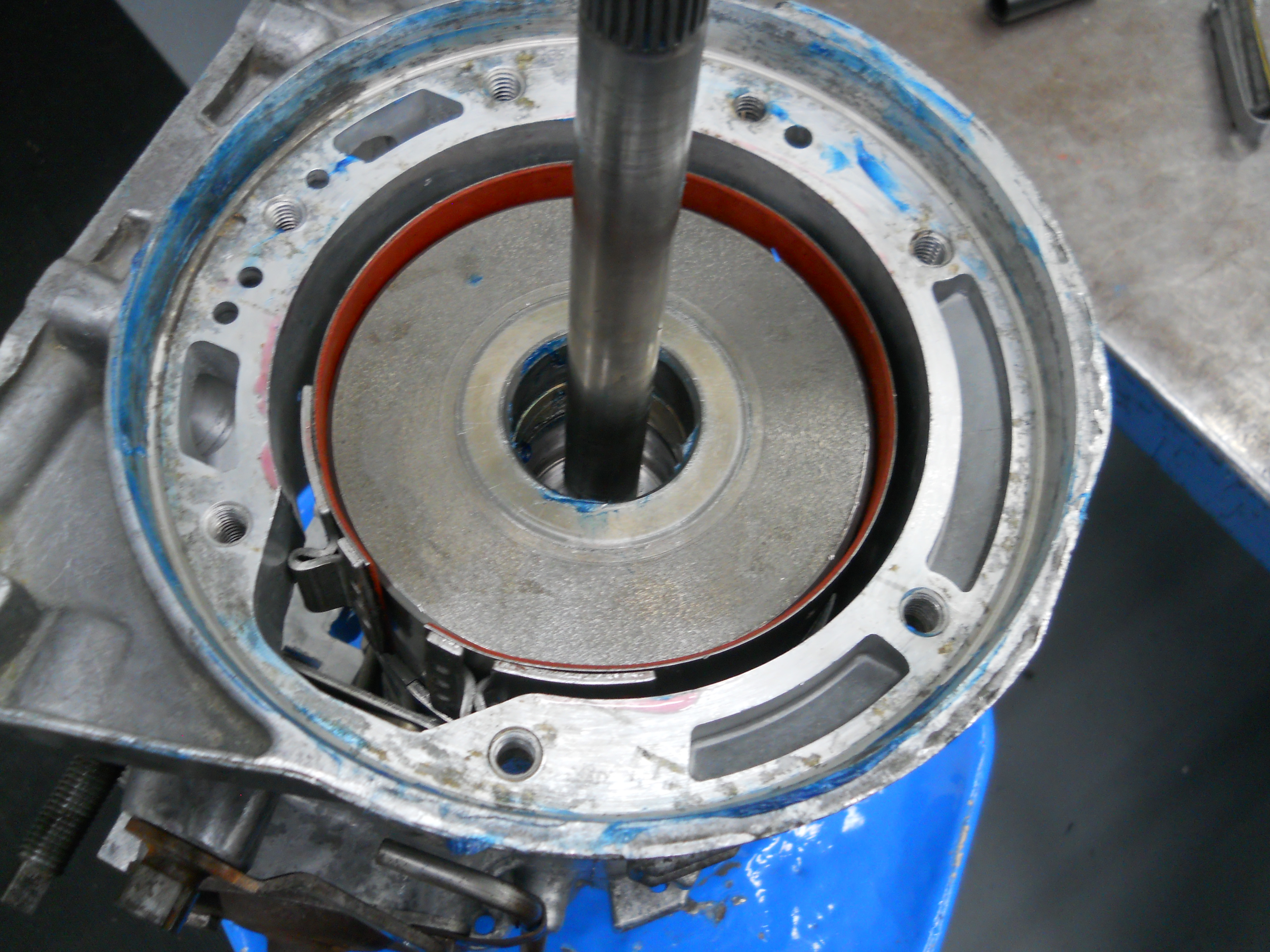
Front Pump Bolts are run down to assemble Front Pump, Bell Housing, and Case.
[C4-DSCN2849] |
Front Pump is held in place by Bell Housing.
[C4-DSCN2850] |
|
|
|

|
Bolts are started by hand one at a time so as to avoid crossthreading.
[C4-DSCN2851] |
Once all the bolts are started, they are all run down evenly until they are seated.
[C4-DSCN2852] |
|
|
|
|
Bolts must be fully seated before they can be torqued.
[C4-DSCN2853] |
Bolts are torqued 28-40 lb-ft.
[C4-DSCN2854] |
|
|
|

|
Bands are adjusted to spec and ready for air check along with direct and forward drum.
[C4-DSCN2856] |
|
|
|
|
|
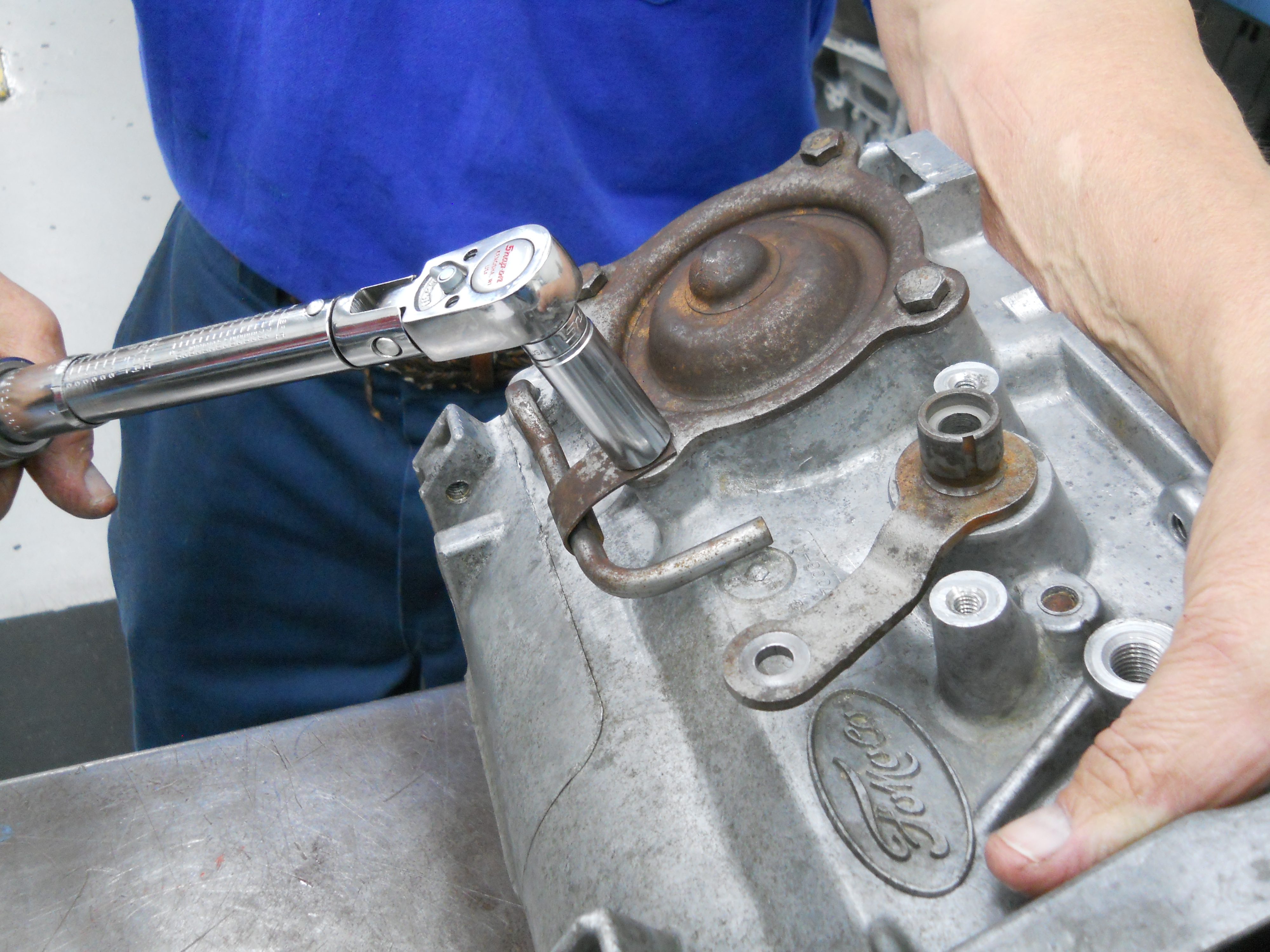
Vaccum Modulator is installed. Note the crowsfoot on the end of the ratchet.
[DSCN2864 / DSCN2865] |
|
|
|
|
Air checking direct and forward drum. A dull thud will will be heard that indicates the clutch has applied correctly. Basically a QC check..
[C4-DSCN2866] |
Air checking the intermediate and low-reverse bands. You can see the bands apply and wrap around their respective drums. Same story as the clutch drums – QC check.
[C4-DSCN2867] |
|
|
|

|
These 8 bolts hold the Valve Body to the case. Torque them to
[C4-DSCN2868] |
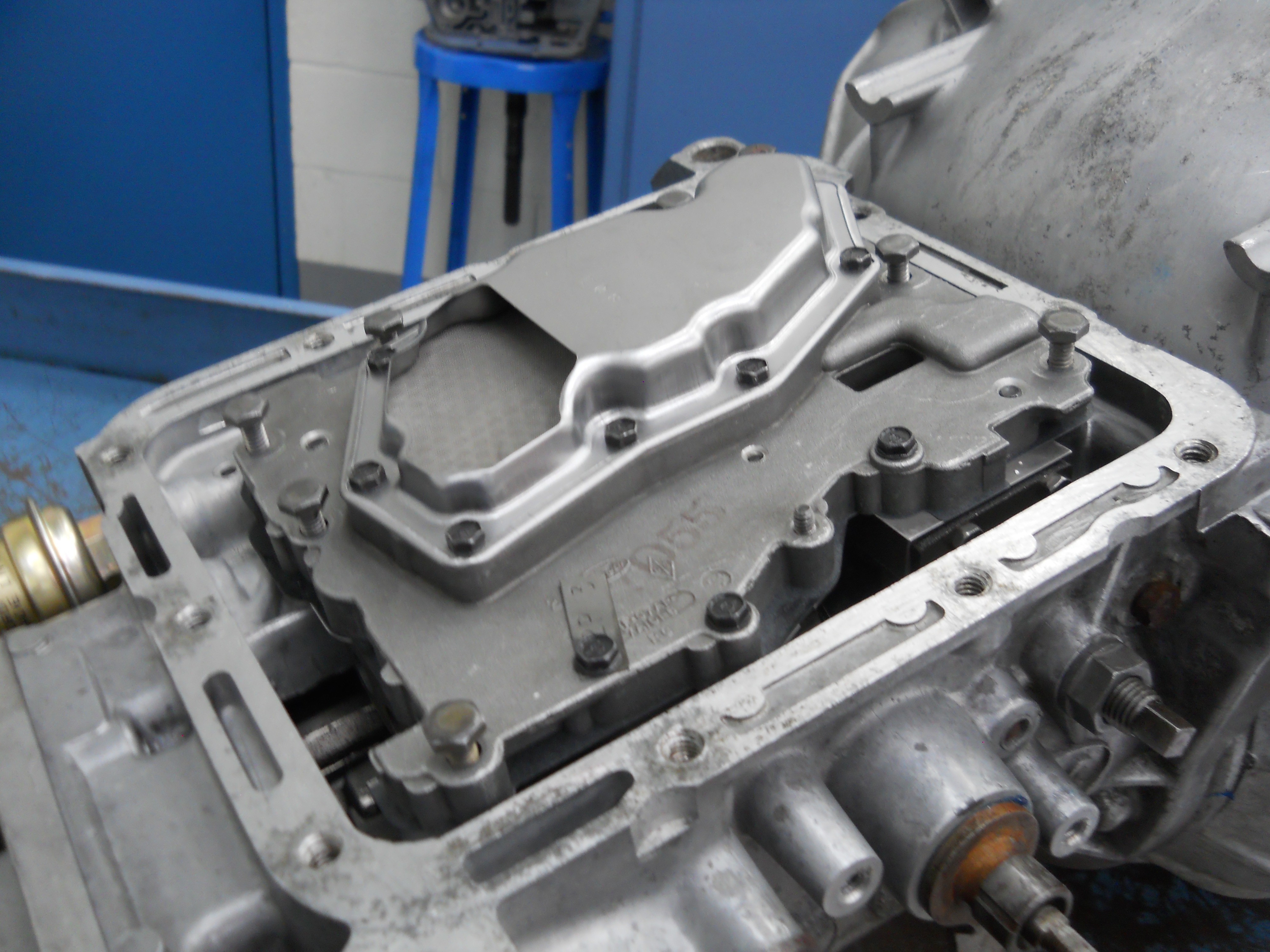
A new gasket is put in place to seal the transmission pan. This is the preferred oil pan gasket. It is a Duraprene gasket far superior to the cork rubber pan gaskets. It is much less likely to leak.
[C4-DSCN2869] |
|
|
|
|
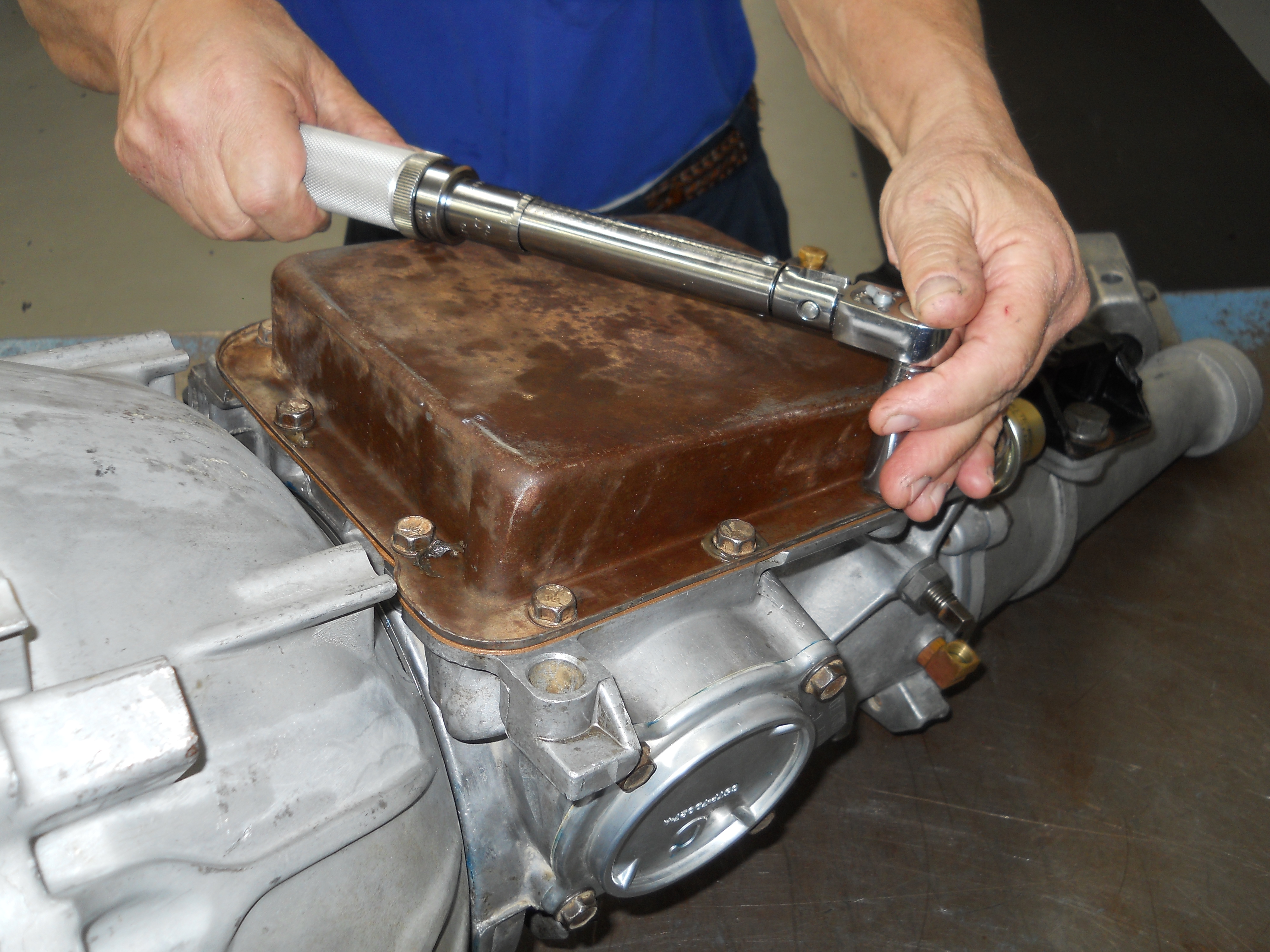
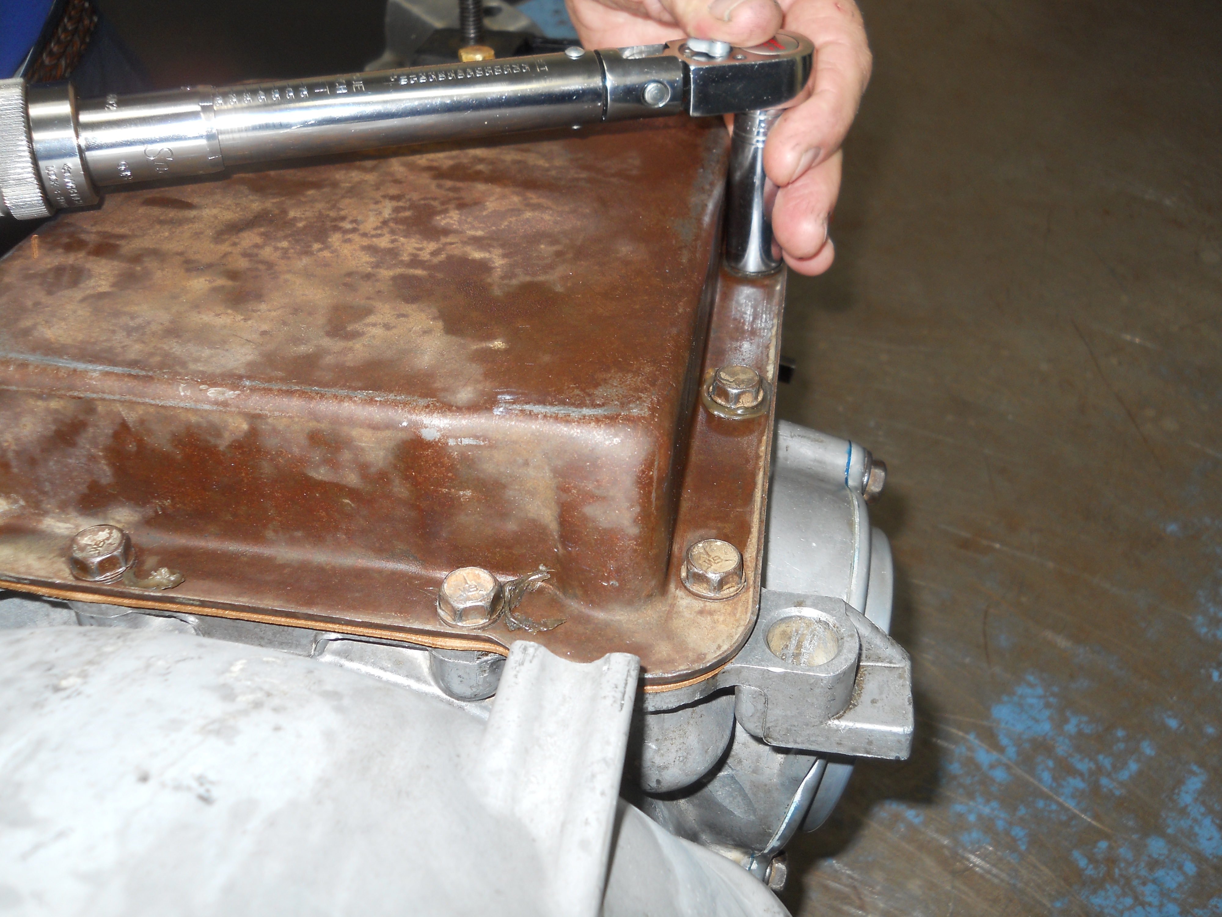
Oil Pan is held to the case by 11 bolts.
[C4-DSCN2870] |
The pan bolts should be torqued 12-16 ft-lbs.
[C4-DSCN2871] |
|
|
|
|
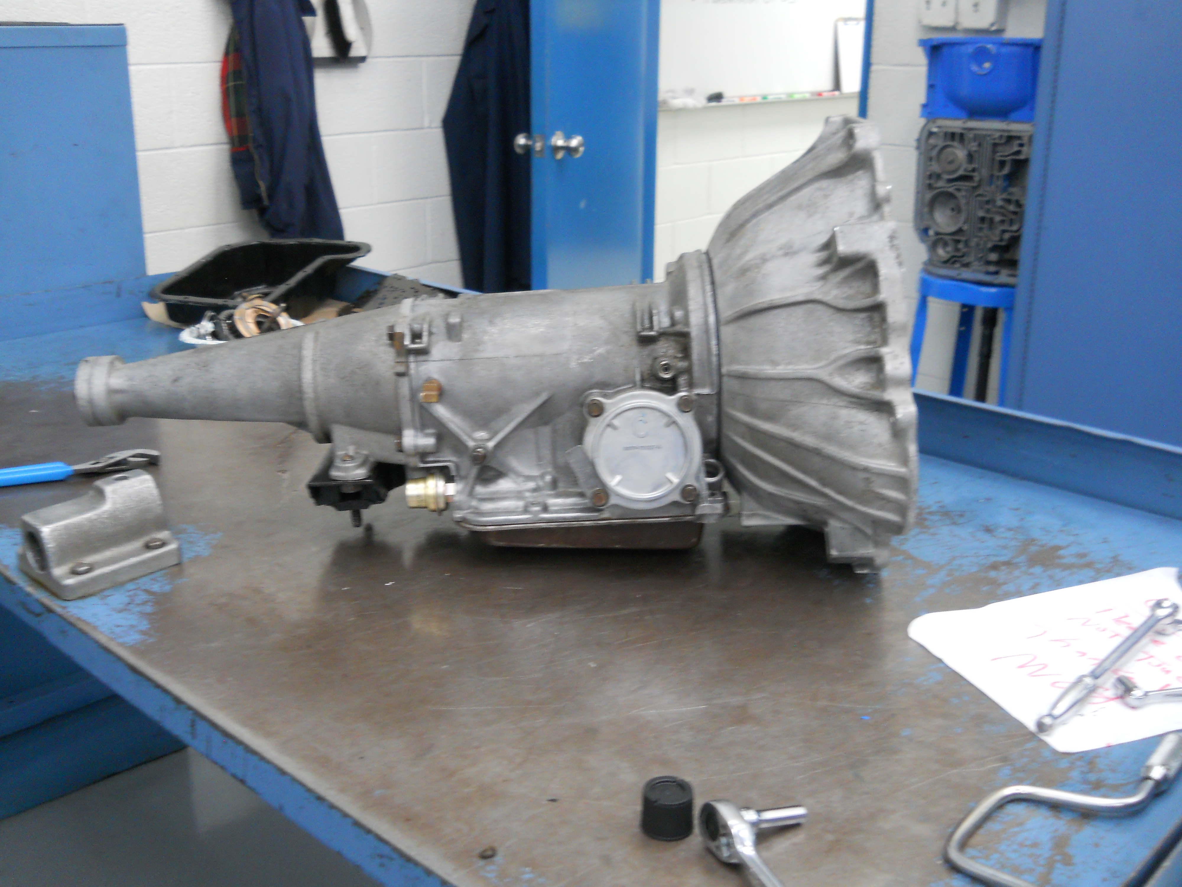
Right side view of completed transmission.
[C4-DSCN2872 / C4-DSCN2873] |
|
|
|
|
Close up of the new "C" code servo for 2nd gear, the larger the servo apply area the firmer the 1-2 shift and the 2-3 shift will be.
[C4-DSCN2874] |
Left side view of completed transmission.
[C4-DSCN2875] |
|
|
|
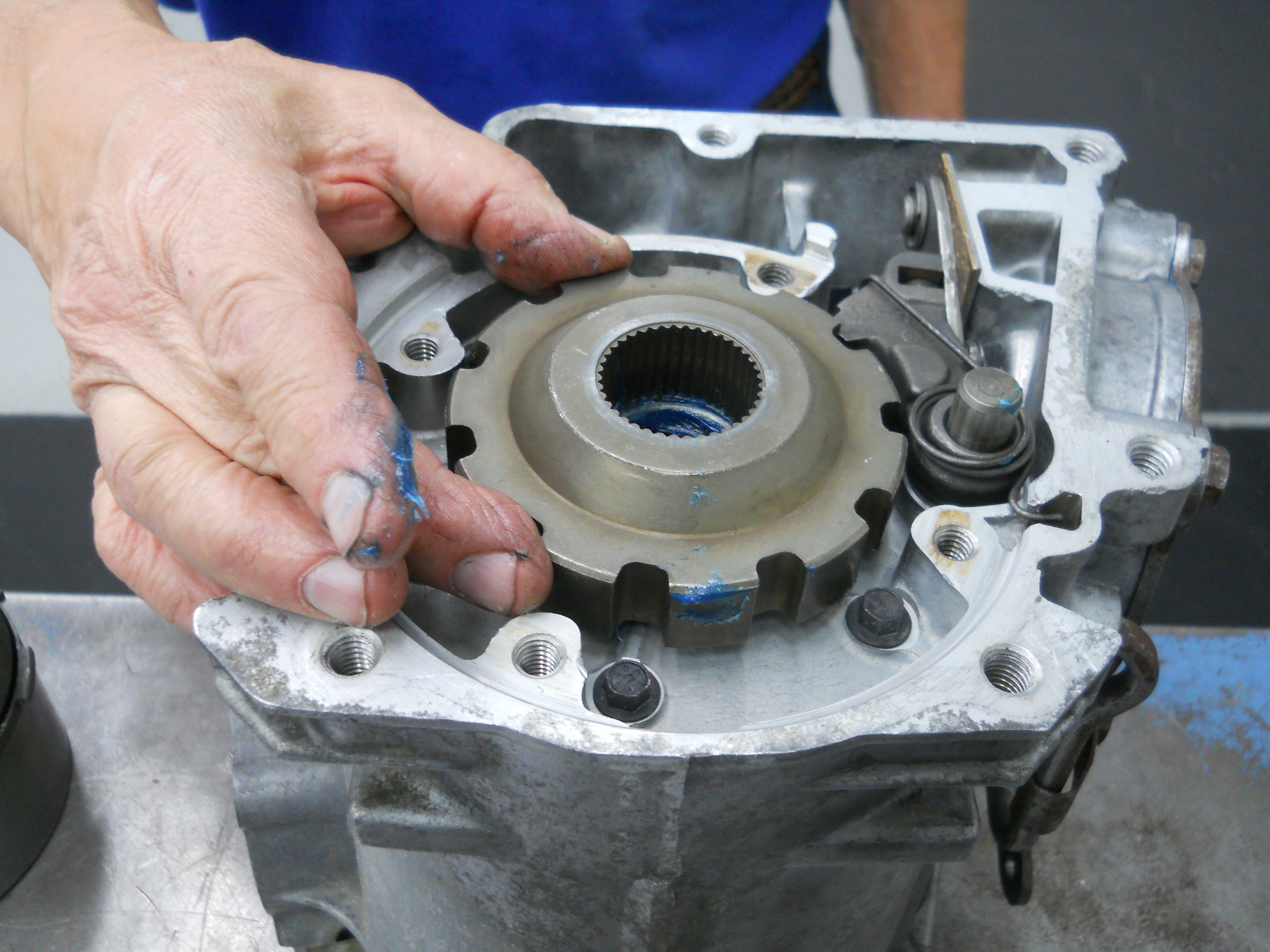
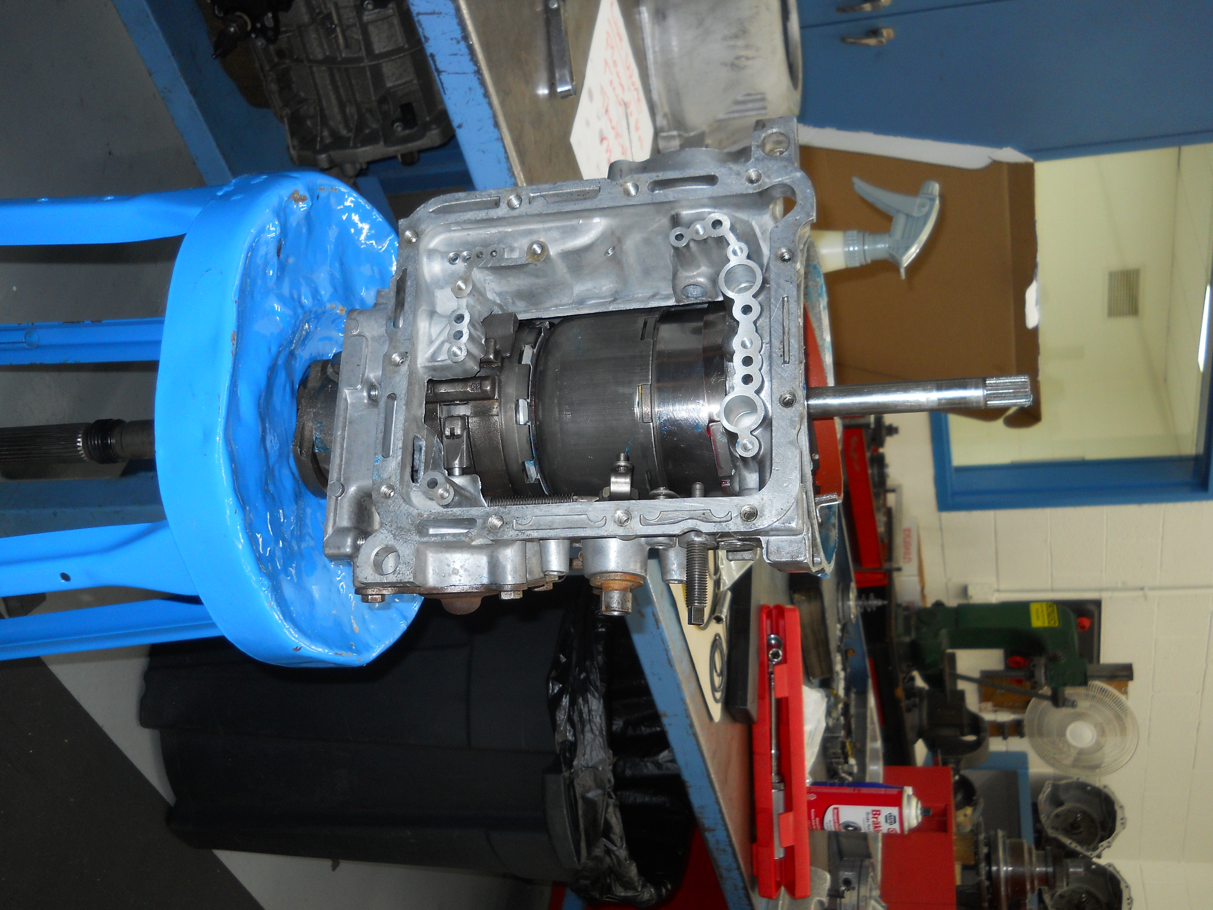
Front view of completed C4 transmission.
[C4-DSCN2876] |
|
|
All rebuild photos © 2021, courtesy of Greg Catanzano except where noted.
- Bob Mannel Mustang & Ford Small Block V8, 1962-1969 (RPM Press, 2014), Appendix I Mustang & Ford Small Block V8, 1962-1969
- TransGo TransGo 47-2 Reprograming Kit
- California Pony Cars C4 Servo Piston and Cover Kit
- Dynamic Racing Transmissions C4 Governor Weight Kit